Display device and lenticular sheet of the display device

a display device and lenticular technology, applied in optics, instruments, electrical devices, etc., can solve the problems of lowering the overall quality of 3d images and the 3d luminance, and achieve the effect of enhancing the quality of 3d images and improving the uniform distribution of luminan

Inactive Publication Date: 2011-07-07
SAMSUNG DISPLAY CO LTD
View PDF15 Cites 30 Cited by
  • Summary
  • Abstract
  • Description
  • Claims
  • Application Information

AI Technical Summary

Benefits of technology

[0010]The present invention provides a display device which can prevent three-dimensional (“3D”) image crossing, improve the uniformity of the distribution of luminance and thus enhance the quality of a 3D image, and a lenticular sheet of the display device.

Problems solved by technology

In recent years, there has been an increasing demand for flat panel display devices such as plasma display panel (“PDP”) devices, plasma-addressed liquid crystal (“PALC”) display panel devices, liquid crystal display (“LCD”) devices and organic light-emitting diode (“OLED”) devices, since conventional cathode ray tube (“CRT”) devices cannot meet the demand for thin and large-scale display devices.
However, conventional methods of displaying 3D images using a lenticular sheet may result in a black matrix moire phenomenon, in which black matrices are viewed at regular intervals of time, and may thus lower the luminance of 3D images, narrow viewing angles, cause color bleeding and eventually lower the overall quality of 3D images.

Method used


Image

  • Display device and lenticular sheet of the display device
  • Display device and lenticular sheet of the display device
  • Display device and lenticular sheet of the display device

Examples


Embodiment Construction

[0037]The present invention will now be described more fully with reference to the accompanying drawings, in which exemplary embodiments of the invention are shown. The invention may, however, be embodied in many different forms and should not be construed as being limited to the embodiments set forth herein. Rather, these embodiments are provided so that this disclosure will be thorough and complete, and will fully convey the concept of the invention to those skilled in the art. In the drawings, like reference numerals indicate like elements, and thus, detailed descriptions thereof will be skipped. In the drawings, the size and relative sizes of layers and regions may be exaggerated for clarity.

[0038]It will be understood that when an element or layer is referred to as being “on,”“connected to” or “coupled to” another element or layer, the element or layer can be directly on, connected or coupled to another element or layer or intervening elements or layers. In contrast, when an el...


PUM


Abstract

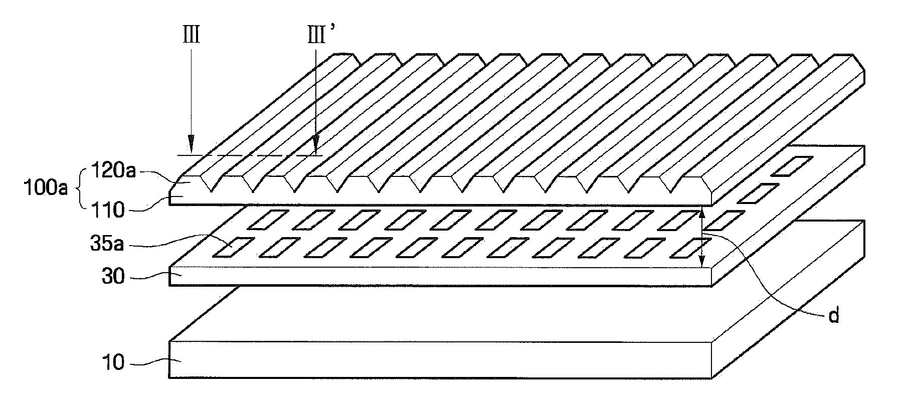
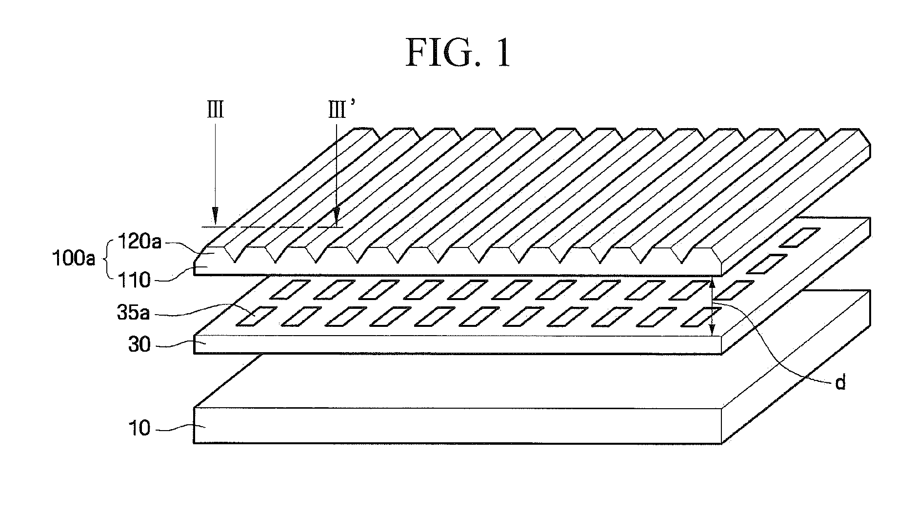
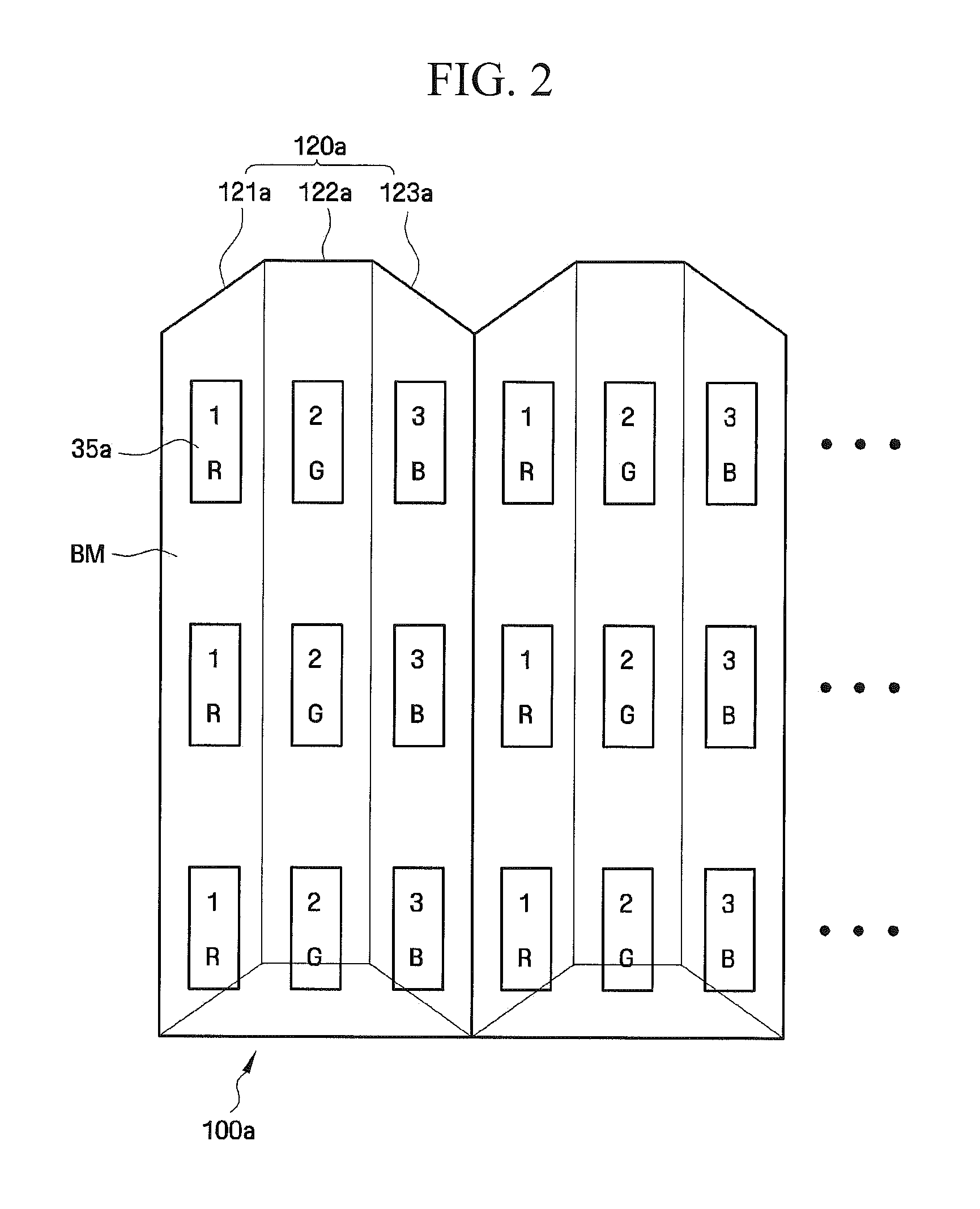
A display device includes a display panel on which a plurality of pixels are arranged in a matrix in a first direction and in a second direction intersecting the first direction, and a lenticular sheet which is disposed above the display panel and includes a plurality of polygonal prism lenses that are arranged in the second direction. Each of the polygonal prism lenses extends in a third direction intersecting the second direction, and includes a plurality of flat surfaces or curved surfaces.

Description

CROSS REFERENCES TO RELATED APPLICATIONS[0001]This application is a continuation-in-part application of U.S. application Ser. No. 12 / 425,549, filed Apr. 17, 2009, which claims priority from Korean Patent Application Nos. 10-2008-0037267 filed Apr. 22, 2008 and 10-2010-0103533 filed Oct. 22, 2010, and all the benefits accruing therefrom under 35 U.S.C. §119, the disclosures of which is incorporated herein by reference in their entirety.BACKGROUND OF THE INVENTION[0002]1. Field of the Invention[0003]The present invention relates to a display device and a lenticular sheet of the display device, and more particularly, to a display device, which can prevent three-dimensional (“3D”) image crossing, improve the uniformity of the distribution of luminance and thus enhance the quality of a 3D image, and a lenticular sheet of the display device.[0004]2. Description of the Related Art[0005]In recent years, there has been an increasing demand for flat panel display devices such as plasma displa...

Claims


Application Information

Patent Timeline
Patent Type & Authority Applications(United States)
IPC IPC(8): G02B27/22G02B27/12G02B30/29
CPCG02B27/2214H04N13/0422H04N13/0415H04N13/0404H04N13/305H04N13/324H04N13/317G02B30/29G02B30/27
Inventor YUN, HAE-YOUNGJUNG, KYUNG-HOLEE, SEUNG-HOONKIM, HEE-SEOPKIM, KYUNG-BAEKIM, JIN-HWANKIM, SUNG-WOONLU, JIANGANG
Owner SAMSUNG DISPLAY CO LTD
Why Eureka
Try Eureka