
Focal plane shutter device and imaging device

Active Publication Date: 2011-07-07
PANASONIC CORP
View PDF9 Cites 18 Cited by
  • Summary
  • Abstract
  • Description
  • Claims
  • Application Information

AI Technical Summary

Benefits of technology

[0010]One object of the technology discussed herein is to provide a focal plane shutter device capable of performing slit exposure photography using a front curtain and a rear curtain, and also capable of reducing a load of a drive source at the time of charging the front curtain and the rear curtain.

Problems solved by technology

In the focal plane shutter device disclosed in JP2004-061865, if taking pictures is made to correspond to electronic front curtain photography, it is necessary that the front curtain runs once at a charge position (i.e., in a state where an aperture is closed), but this raises a problem in that the live view, for example, needs to be stopped.
Moreover, the focal plane shutter device disclosed in JP2007-316503 does not include the front curtain, and it is therefore not possible to perform a slit exposure using the front curtain and the rear curtain.

Method used


Image

  • Focal plane shutter device and imaging device
  • Focal plane shutter device and imaging device
  • Focal plane shutter device and imaging device

Examples


first embodiment

[0048]1: Digital Camera

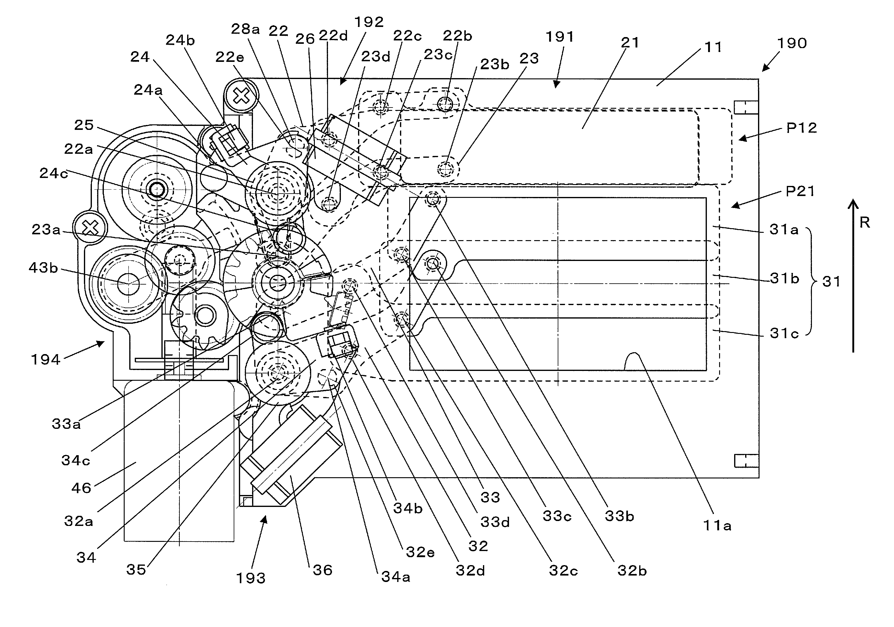
[0049]By using drawings, an overview of a digital camera 1 on which a focal plane shutter device 190 is mounted will be explained. It is noted that the focal plane shutter device 190 can be mounted on cameras other than the digital camera 1 of the embodiments.

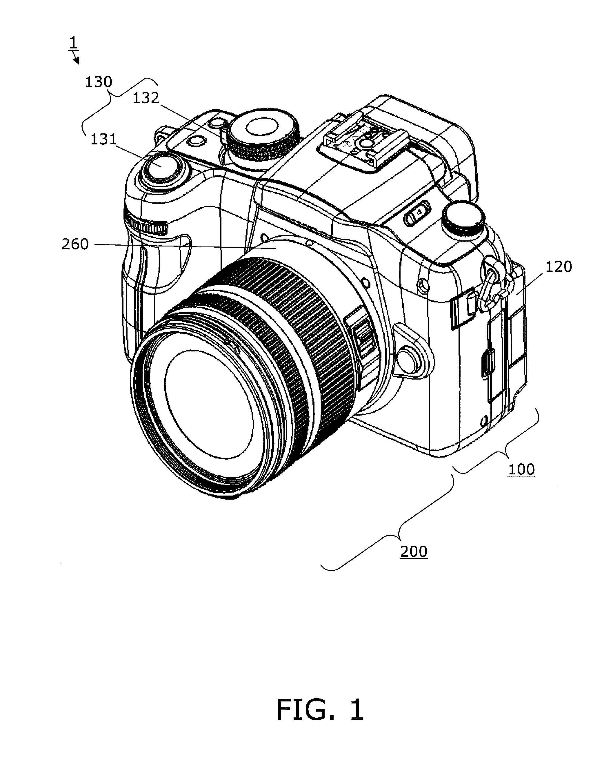
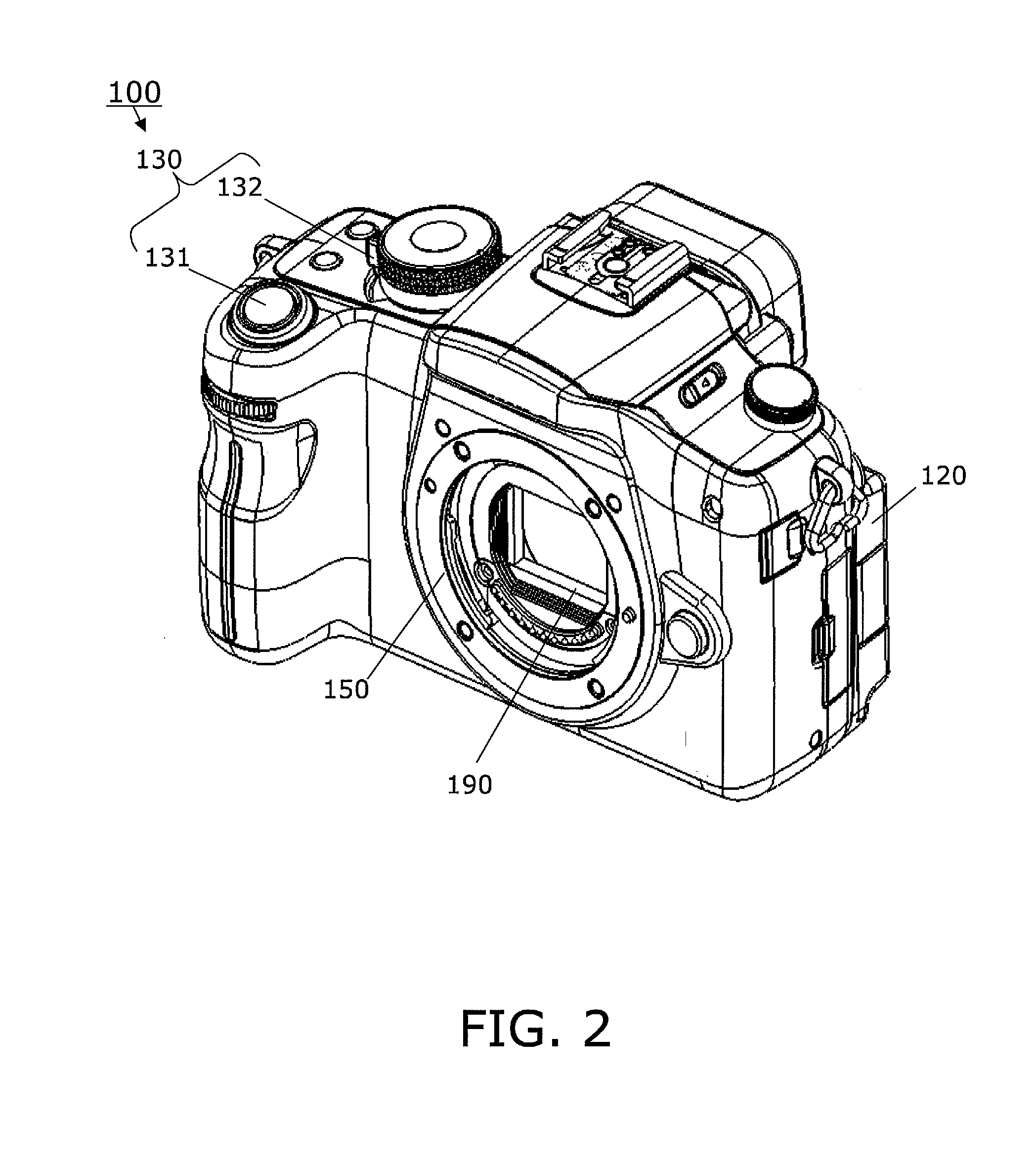
[0050]FIG. 1 is a perspective view of the digital camera 1 according to the first embodiment. FIG. 2 is a perspective view of a camera body 100. FIG. 3 is a functional block diagram of the digital camera 1.

[0051]The digital camera 1 is an interchangeable-lens-type digital camera that includes the camera body 100 and a lens unit 200 attachable to the camera body 100.

[0052]FIG. 4 is a simplified cross section of the digital camera 1. FIG. 5 is a rear view of the camera body 100. The camera body 100 mainly includes: a Complementary Metal Oxide Semiconductor (CMOS) image sensor 110, a CMOS circuit board 113, a camera monitor 120, an operation part 130, a main circuit board 142 including a camera controller 14...

second embodiment

[0192]Subsequently, a second embodiment will be explained. In the second embodiment, points different from those in the first embodiment will be mainly explained, and the explanations for the common configuration in the first and second embodiments are omitted. Moreover, the same reference numerals are assigned to the configurations having the substantially same functions as those in the first embodiment.

[0193]1: Digital Camera

[0194]The digital camera 1 according to the second embodiment employs a focal plane shutter device 290, instead of the focal plane shutter device 190, and except for this, the digital camera 1 is basically configured similarly to the first embodiment.

[0195]2: Configuration of the Focal Plane Shutter Device

[0196]By using FIGS. 23 to 32, the focal plane shutter device 290 according to the second embodiment will be explained. FIG. 23 is a state diagram of the focal plane shutter device 290 obtained when the rear curtain 31 completes running. FIG. 24 is a detailed...


PUM


Abstract

A focal plane shutter device is disclosed that includes a shutter base plate, a front curtain, a first urging member, a rear curtain, a second urging member, and a charge mechanism. The shutter base plate defines an opening. The front curtain is moved between different positions by the first urging member to cover and uncover the opening. The rear curtain is moved between different positions by the second urging member to cover and uncover the opening. The charge mechanism applies a first force to resist an urging force by the first urging member and a second force to resist an urging force by the second urging member. The first force applied by the charge mechanism terminates at a different time than the second force applied by the charge mechanism.

Description

CROSS-REFERENCE TO RELATED APPLICATIONS[0001]This application claims priority under 35 U.S.C. §119 to Japanese Patent Application No. 2010-000958, filed on Jan. 6, 2010, and Japanese Patent Application No. 2010-279842, filed on Dec. 15, 2010. The entire disclosure of Japanese Patent Applications No. 2010-000958 and Japanese Patent Application No. 2010-279842 are hereby incorporated herein by reference.BACKGROUND[0002]1. Technical Field[0003]The technology disclosed herein generally relates to a focal plane shutter device. More specifically, the technology disclosed herein relates to a focal plane shutter device used in an imaging device.[0004]2. Background Information[0005]Japanese Patent Laid-Open Publication JP2004-061865 discloses a focal plane shutter device having a so-called normally open function.[0006]Japanese Patent Laid-Open Publication JP2007-316503 discloses a focal plane shutter device corresponding to electronic front curtain photography. This focal plane shutter devic...

Claims


Application Information

Patent Timeline
IPC IPC(8): G03B9/40
CPCG03B9/40G03B19/12G03B17/14
Inventor SHINTANI, DAI
Owner PANASONIC CORP
Learn More