
Method and apparatus for locating and visualizing a target in relation to a focal point of a treatment system

Active Publication Date: 2011-07-07
EDAP TMS FRANCE
View PDF14 Cites 14 Cited by
  • Summary
  • Abstract
  • Description
  • Claims
  • Application Information

AI Technical Summary

Benefits of technology

[0012]The present invention therefore sets out to remedy the disadvantages set forth above by proposing a novel technique which offers the advantage of facilitating the locating operation of an anatomic target by means of an ultrasound imaging system, whilst allowing the precise positioning of a treatment system using acoustic pressure waves to treat said target.
[0043]an ultrasound imaging system comprising an ultrasound probe and image forming means allowing the target and focal point to be visualized at least on one screen.

Problems solved by technology

However, in general, imaging systems of X-ray type are costly, complex and cumbersome which means that it appears difficult to use these in combination with treatment systems.
Also, the monitoring of the alignment of the target and focal point using X-rays requires continuous irradiation of the patient, which is harmful for the patient and nursing staff.
This constraint is extremely penalising for the operator, insofar as it appears difficult in some cases to find the target having regard to the limited movements of the probe and / or patient to obtain the target and focal point in one same image.
Also, it appears difficult to adjust the plane of the ultrasound image slice relative to the anatomy of the observed target to obtain the best possible definition of the contours or inner side of the target.
The main drawback with this technique concerns the fact that imaging is not carried out in real time, since imaging is conducted during a phase prior to the treatment phase.
This technique does not allow monitoring and confirmation of the correct positioning of the therapy device in relation to the targeted region.
This approach is based on full immobility of the patient during the treatment phase, which appears difficult to implement in practice.

Method used


Image

  • Method and apparatus for locating and visualizing a target in relation to a focal point of a treatment system
  • Method and apparatus for locating and visualizing a target in relation to a focal point of a treatment system
  • Method and apparatus for locating and visualizing a target in relation to a focal point of a treatment system

Examples


Embodiment Construction

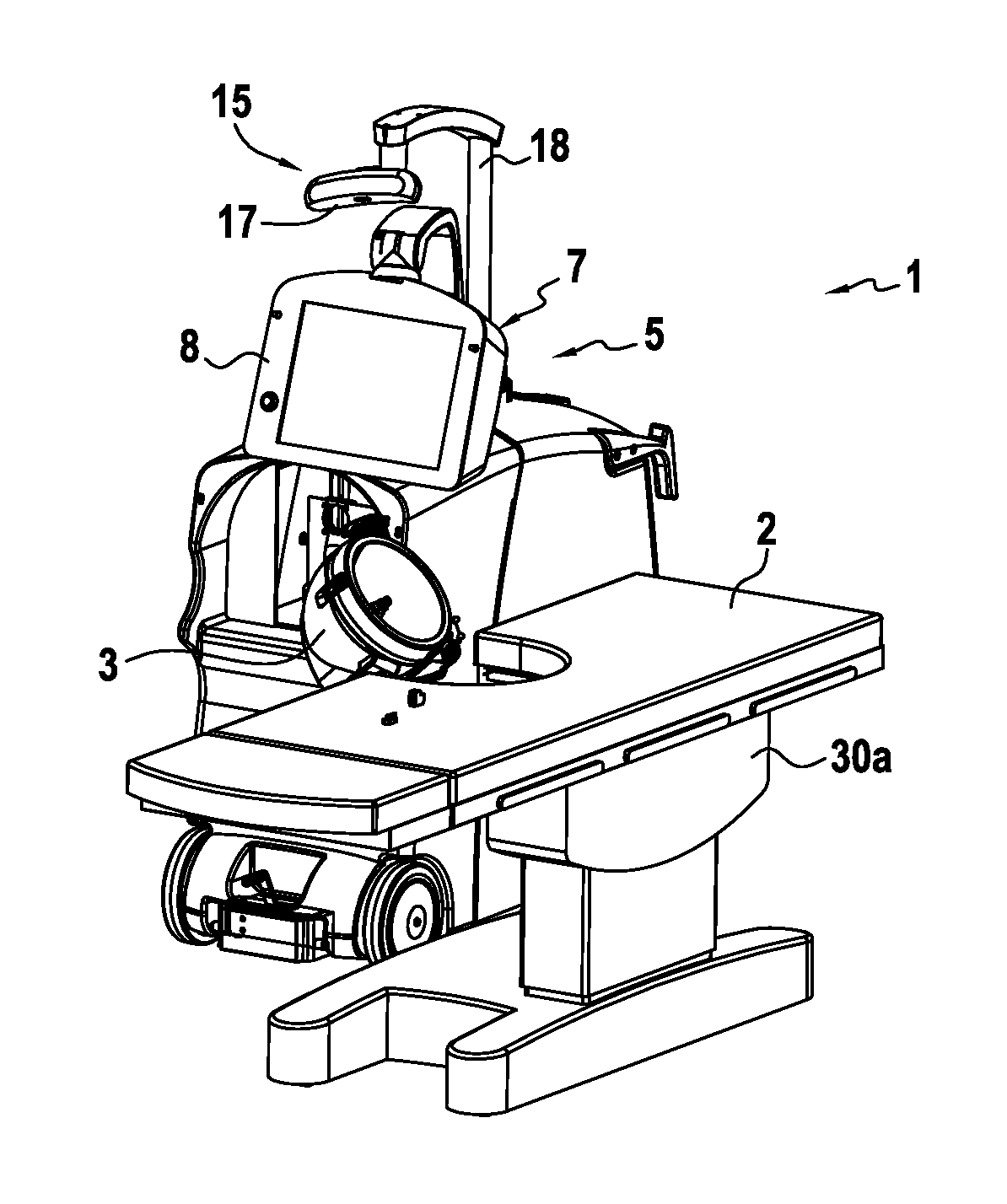
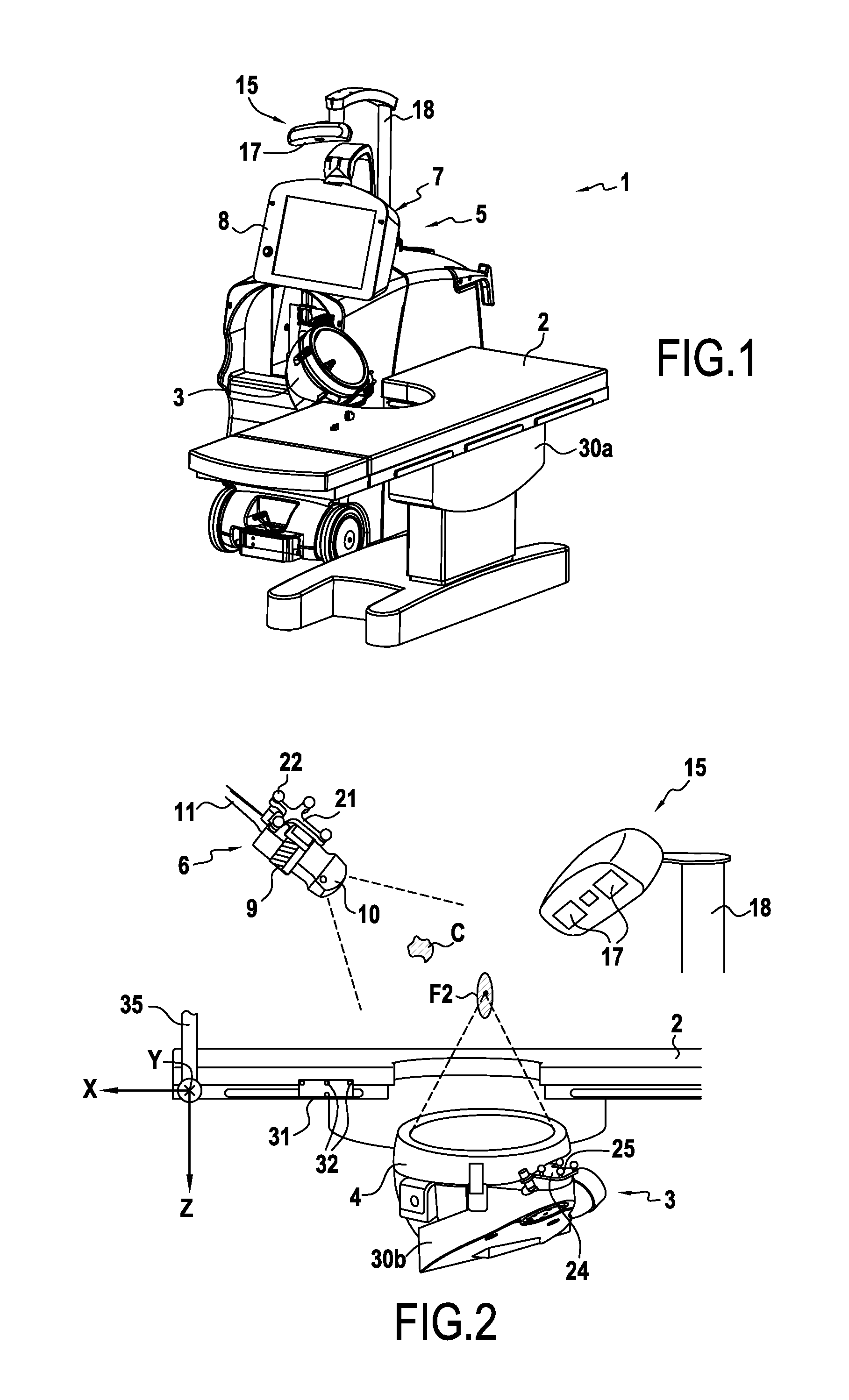
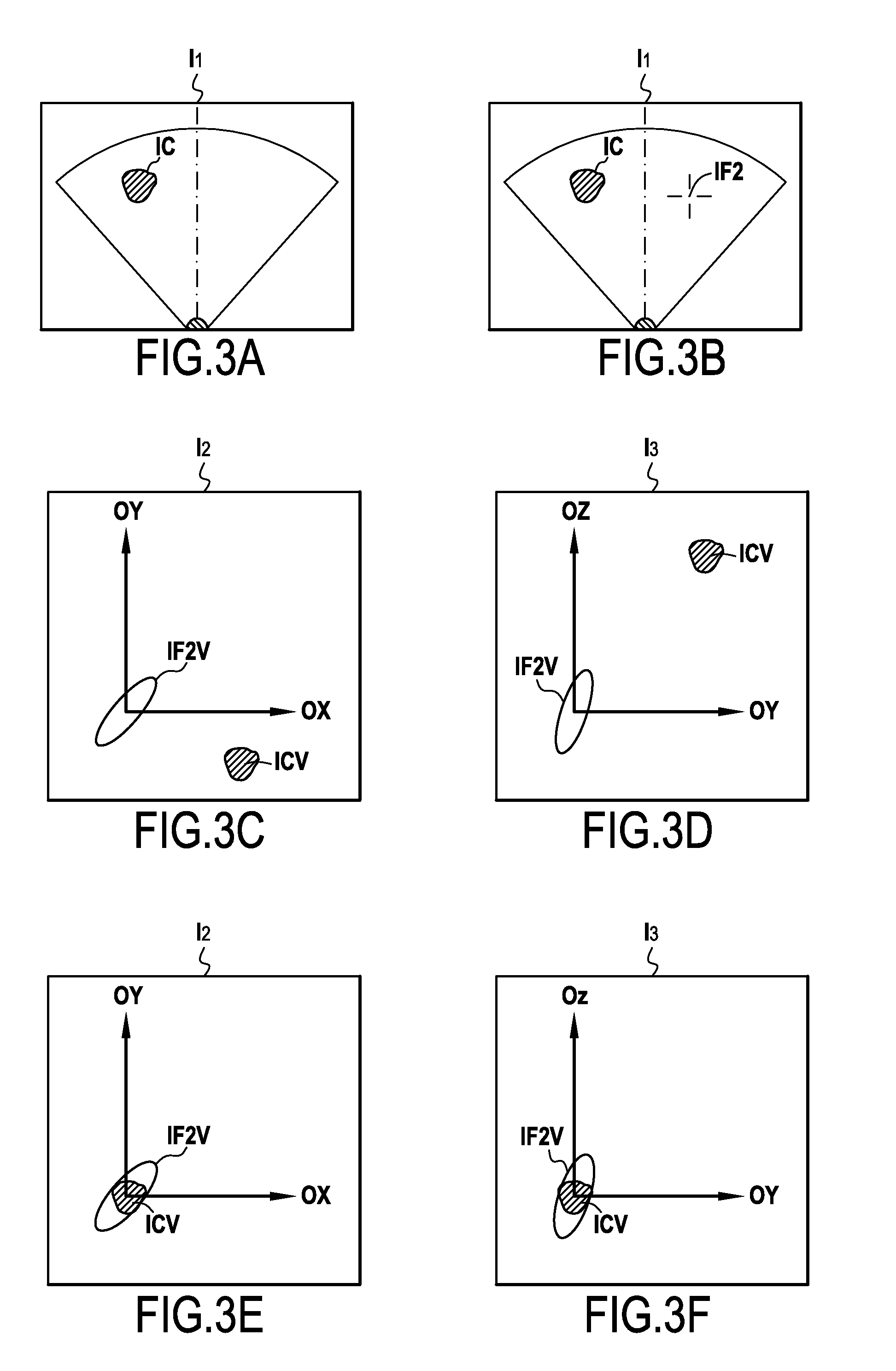
[0070]FIGS. 1 and 2 illustrate apparatus 1 for the locating and visualization of a target C such as an anatomic structure or concrement belonging to a mammal, a human being in particular. As is conventional, the apparatus 1 comprises a table 2 supporting a patient carrying the target C. The target C is intended to be treated by means of a treatment system 3 using acoustic pressure waves directed towards a focal point F2. Said treatment system 3 ensures the focusing of shock waves or ultrasound waves. As is conventional, this treatment system 3 comprises a generator 4 designed to focus the ultrasound waves or shock waves on a focal point F2. The treatment system 3 is not described in further detail since it is well known to the person skilled in the art and is not specifically part of the subject matter of the invention.

[0071]The apparatus 1 conforming to the invention also comprises an ultrasound imaging system 5 comprising an ultrasound probe 6 connected to image forming means 7 on...


PUM


Abstract

A method for locating and visualizing a target (C) in relation to a focal point (F2), in a mammal, particularly a human body, including the steps of forming an ultrasound probe mobile in space, mechanically independent of a treatment system and located by a remote locating system, ensuring the simultaneous recording firstly of an ultrasound image in which the image of the target appears, and secondly of the position of the ultrasound probe, in the recorded ultrasound image, selecting the position of the image of the target to determine the virtual position of the target (C), simultaneously determining firstly the position of the focal point (F2) by means of the remote locating system, and secondly the position of the means displacing the target and / or treatment system, and calculating the displacement values for the displacing means, to cause the virtual position of the target (C) to coincide with the focal point (F2).

Description

BACKGROUND OF THE INVENTION[0001]The subject matter of the invention relates to the technical field of visualizing and locating an anatomic structure or concrement in the body of a mammal, a human being in particular.[0002]The locating and visualization of anatomic structures or concrements generally designated as targets in the remainder of the description, are currently performed using imaging devices based on different methods such as echography methods using ultrasound, or tomography methods based on X-rays, or on magnetic resonance (MRI). These imaging devices therefore allow the positioning of a therapeutic treatment system in relation to the target for treatment thereof by focusing shock waves or ultrasound waves on a focal point.[0003]In the state of the art, a treatment apparatus is known from document DE 10 2006 060070, which comprises a system for treatment with acoustic pressure waves, using an imaging system of X-ray type, even if said document provides for the possible...

Claims


Application Information

Patent Timeline
IPC IPC(8): A61B8/14
CPCA61B17/2255A61B17/2256A61B19/5244A61B2019/5289A61B2019/5255A61B2019/5259A61B2019/5276A61B2019/507A61B34/20A61B2034/107A61B2034/2055A61B2034/2059A61B2090/364A61B2090/378
Inventor PEYRARD, ANDREVURPILLOT, CLAIRECHATRE, RENE
Owner EDAP TMS FRANCE
Learn More