
Method and Network for Transmitting Data in a Wireless Network with Fixed Transmission Intervals

Active Publication Date: 2011-07-07
MITSUBISHI ELECTRIC RES LAB INC
View PDF8 Cites 19 Cited by
  • Summary
  • Abstract
  • Description
  • Claims
  • Application Information

AI Technical Summary

Benefits of technology

[0009]Then, the set of slaves is partitioned into subsets of slaves according to the channel conditions. The master assigns, to each slave, a transmission rate in a low to high order according to the channel conditions.
[0010]The slaves transmit data to the master in the low to high order between t

Problems solved by technology

However, that method is only applicable for wireless local area networks (LAN), and the decision of whether or not to use the relay is made at the source node.
That method does not consider the use of relay nodes.

Method used


Image

  • Method and Network for Transmitting Data in a Wireless Network with Fixed Transmission Intervals
  • Method and Network for Transmitting Data in a Wireless Network with Fixed Transmission Intervals
  • Method and Network for Transmitting Data in a Wireless Network with Fixed Transmission Intervals

Examples


Embodiment Construction

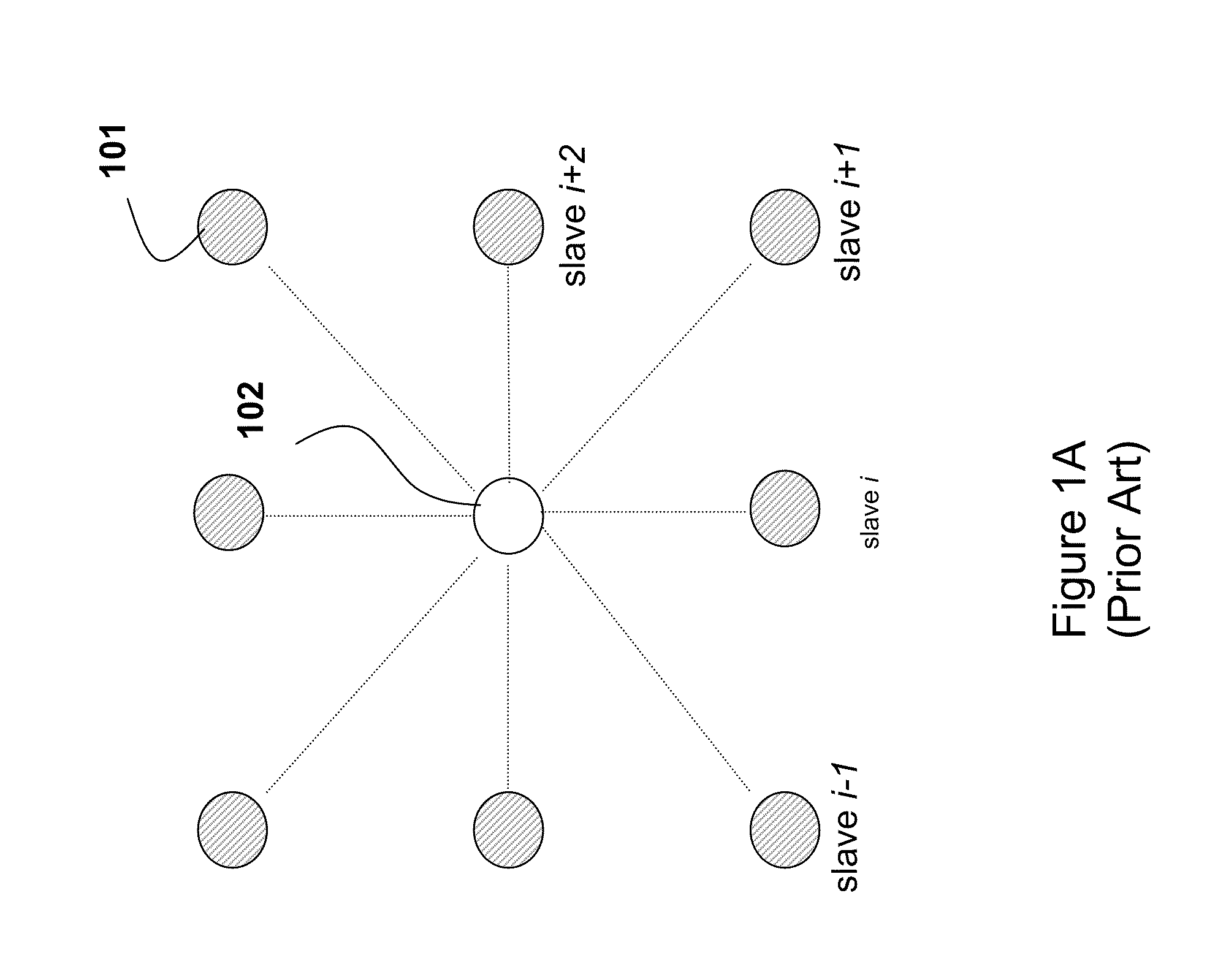
[0018]FIG. 2A shows a wireless star network according to embodiments of our invention. The network can be designed according to the IEEE 802.15.4 standards.

[0019]The network includes a set of N slave nodes (slaves) 201, and a master node (master) node 202. Average channel condition between slave i and the master is αi, m 203. The slaves can use time division multiple access (TDMA) that allows only a single slave node to transmit at a given time. Alternatively, the slaves can also use orthogonal frequency division multiple access (OFDMA), or code division multiple access (CDMA), which enables multiple, but perhaps not all, slaves to transmit their data to the master concurrently. It is understood that the data can be transmitted as packets. It is also understood that a combination of the aforementioned multiple access technology can be used, such as TDMA and OFDMA.

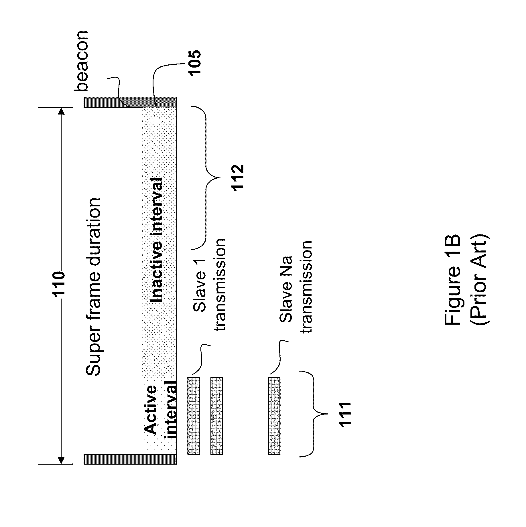
[0020]As shown in FIGS. 2B and 3B, the superframe intervals 210 is partitioned into an active interval T 211 and an inact...


PUM


Abstract

A wireless network master node periodically broadcasts beacons that specify a structure of a following fixed length superframe. Slave nodes determine a channel condition between each slave and the master. Then, the set of slaves is partitioned into subsets of slaves according to the channel conditions. The master assigns, to each slave, a transmission rate in a low to high order according to the channel conditions, and the slaves transmit data to the master in the low to high order between two consecutive beacons, wherein the subsets of slaves with a higher transmission rate also receive the data from the subsets of slaves with a lower transmission rate, and wherein a slave with a higher transmission rate includes a part of or all the data from a slave with a lower transmission rate.

Description

RELATED APPLICATIONS[0001]This U.S. Patent Application is a Continuation-in-Part of MERL-2199 U.S. patent application Ser. No. 12 / 651,472, entitled, “Cooperative Relay Communication in Wireless OFDMA Star Networks,” filed Jan. 3, 2010, by Yim et al. incorporated herein by reference.FIELD OF THE INVENTION[0002]This invention relates in general to wireless communication networks, and in particular to dynamic assignment of network resources to cooperating network nodes to improve communication reliability.BACKGROUND OF THE INVENTION[0003]U.S. Pat. No. 7,330,457 describes a cooperative wireless communication network where a wireless source node (source) uses a relay node to forward data to a destination node (destination) if the relaying reduces delay. Otherwise, the traffic is sent directly from the source to the destination. Transmission rates on links between the source, relay and destination depend on channel conditions. However, that method is only applicable for wireless local are...

Claims


Application Information

Patent Timeline
IPC IPC(8): G06F15/16
CPCH04B7/15592H04B7/2606H04W84/18H04W84/047H04W72/121
Inventor YIM, RAYMONDTAO, ZHIFENGSAHINOGHU, ZAFERPUN, MAN-ON
Owner MITSUBISHI ELECTRIC RES LAB INC
Features
  • Generate Ideas
  • Intellectual Property
  • Life Sciences
  • Materials
  • Tech Scout
  • Unparalleled Data Quality
  • Higher Quality Content
  • 60% Fewer Hallucinations
Learn More