Molten metal containment structure having movable cover

a technology of metal containment and movable cover, which is applied in the direction of caps, furniture, lighting and heating equipment, etc., can solve the problems of crowding the opening by the cover, difficulty in lifting, and discomfort or burns

Inactive Publication Date: 2011-07-14
NOVELIS INC
View PDF6 Cites 12 Cited by
  • Summary
  • Abstract
  • Description
  • Claims
  • Application Information

AI Technical Summary

Problems solved by technology

A disadvantage of providing such removable or openable covers is that their undersides, i.e. the surfaces facing the molten metal, become very hot in use and operators of the equipment may be exposed to heat radiating from the undersides when the covers are lifted, resulting in discomfort or burns.
Moreover, a simple hinge may result in crowding of the opening by the cover, even when the cover is fully retracted.
As a result, such covers can be quite heavy, so the lifting may be difficult when attempted by hand, and damage may be caused (particularly to integral heaters) if the covers are simply allowed to fall back into place.
However, the operator is exposed directly to the hot underside of the cover when the cover is raised.
However, the apparatus is costly and requires clear floor space around the troughs or runners.

Method used


Image

  • Molten metal containment structure having movable cover
  • Molten metal containment structure having movable cover
  • Molten metal containment structure having movable cover

Examples


Embodiment Construction

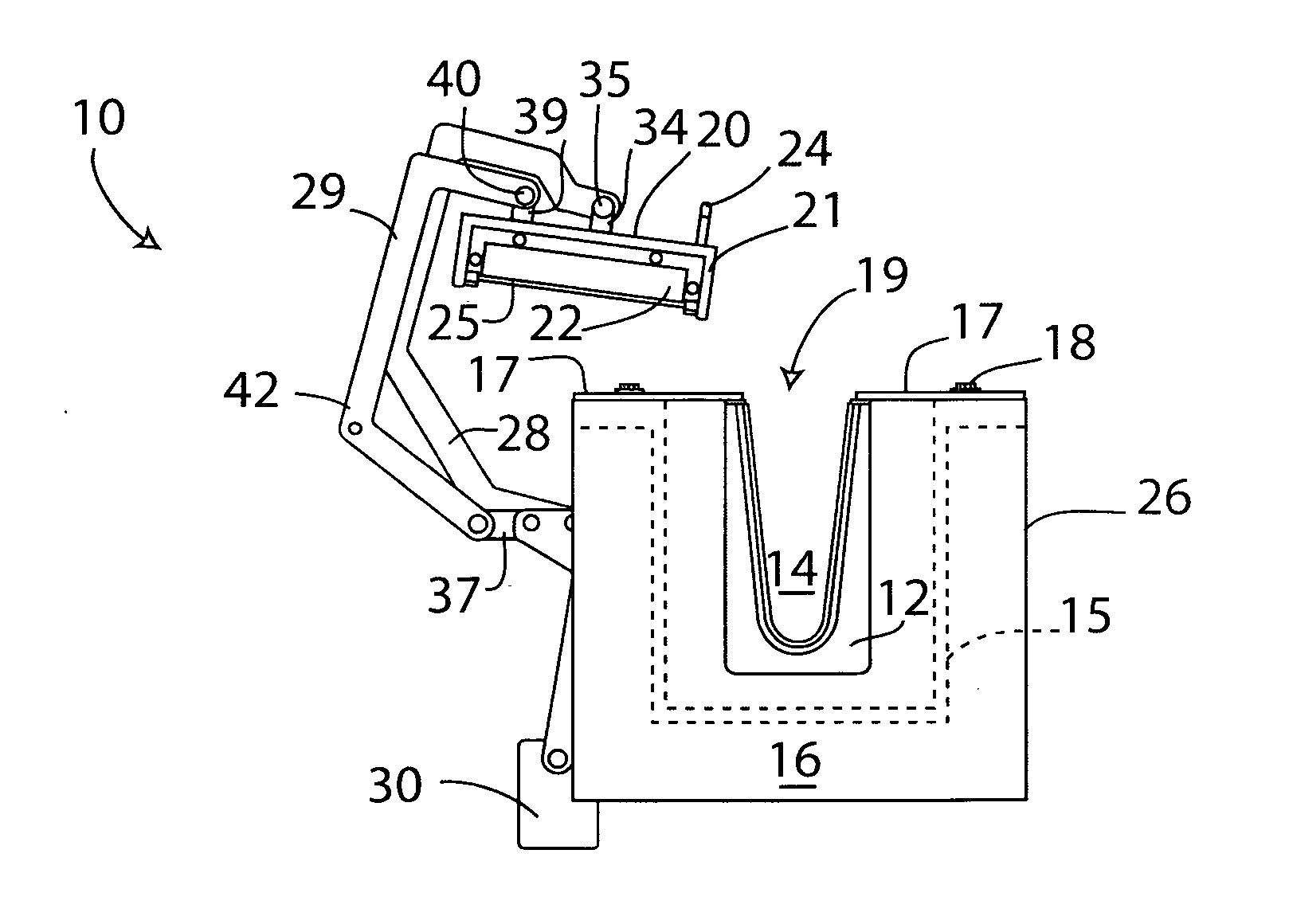
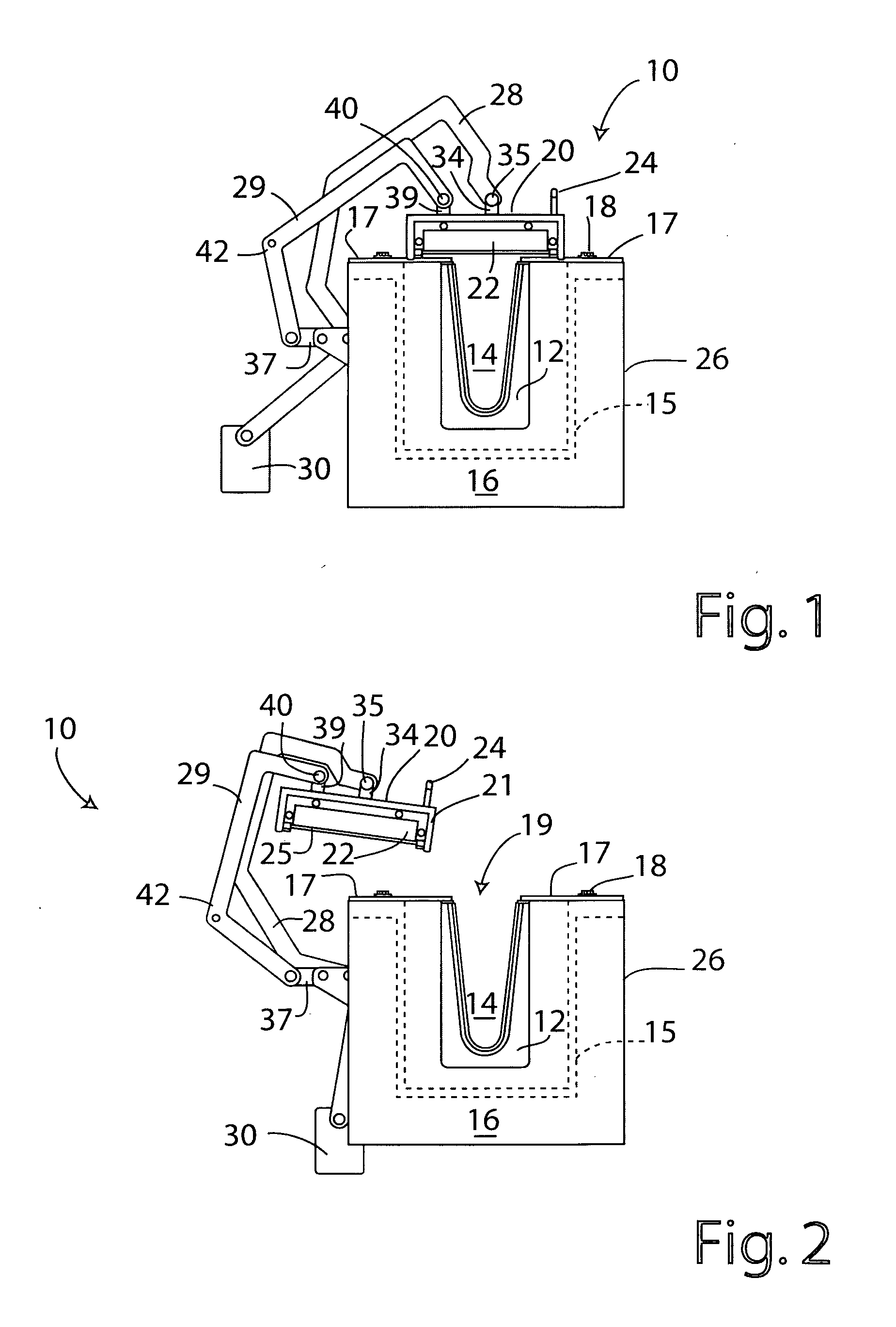
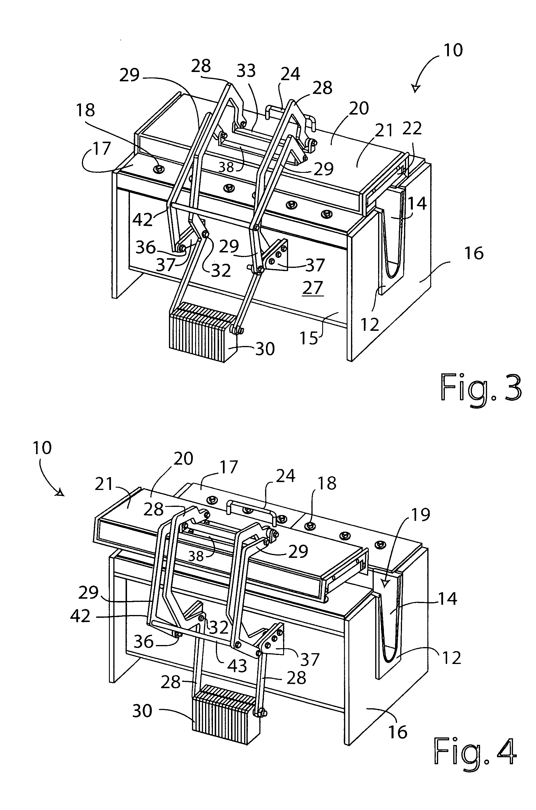
[0011]An exemplary embodiment of the invention provides a molten metal containment structure, including a vessel, preferably provided with an outer metal casing, having an internal volume for containing molten metal and an open upper end. The structure further includes a cover for the vessel having an underside facing the internal volume, the cover being movable between a closed position, covering the open upper end of the vessel with the underside of the cover, and an open position in which said cover is remote from the open upper end of the vessel to allow access to the internal volume from one side of the structure. The cover is attached to a support by at least one elongated lifting arm (preferably two or more) and at least one elongated rotation control arm (preferably two or more). The lifting arm operates to guide the cover from the closed position to the open position, and vice versa, and the rotation control arm operates to control horizontal axial pivoting of the cover dur...


PUM

PropertyMeasurementUnit
temperatureaaaaaaaaaa
angle of tiltaaaaaaaaaa
internal volumeaaaaaaaaaa

Abstract

An exemplary embodiment of the invention provides a molten metal containment structure, including a vessel having an internal volume for containing molten metal and an open upper end. The structure further includes a cover for the vessel having an underside facing the internal volume, the cover being movable between a closed position, covering the open upper end of the vessel with the underside of the cover, and an open position in which the cover is remote from the open upper end of the vessel to allow access to the internal volume from one side of the structure. The cover is attached to at least one lifting arm (preferably two or more) and at least on rotation control arm (preferably two or more). The lifting arm(s) operates to guide the cover from the open position to the closed position, and vice versa. The rotation control arm(s) operates to control pivoting of the cover during movement from the closed position to the open position, and vice versa, to prevent exposure of the underside of the cover, which in operation is very hot, to a person positioned adjacent to the structure at the aforesaid one side thereof. The lifting arm(s) and / or rotation control arm(s) provide a force that at least partially counterbalances a weight of the cover.

Description

CROSS-REFERENCE TO RELATED APPLICATION[0001]This application claims the priority right of prior U.S. provisional patent application Ser. No. 61 / 335,986 filed Jan. 13, 2010 by applicants named herein. The entire contents of U.S. application Ser. No. 61 / 335,986 are specifically incorporated herein by this reference for all purposes.BACKGROUND OF THE INVENTION[0002]I. Field of the Invention[0003]This invention relates to molten metal containment structures used for conveying, treating or holding molten metals, incorporating refractory or ceramic molten metal containment vessels, such as troughs or crucibles. More particularly, the invention relates to the provision of covers for such structures and vessels.[0004]II. Background Art[0005]Molten metal containment structures, e.g. metal-conveying troughs or launders, are often required during metal treatment or casting operations to convey molten metal from one location, such as a metal melting furnace, to another location, such as a casti...

Claims


Application Information

Patent Timeline
Patent Type & Authority Applications(United States)
IPC IPC(8): B65D55/00B65D43/26
CPCB22D41/00B22D41/01F27D2001/185F27D1/18F27D1/1808F27B14/12F27D2005/0075F27D2005/0081Y02P10/20B22D41/14
Inventor REEVES, ERIC W.
Owner NOVELIS INC
Why Eureka
Try Eureka