Magnetic Actor and a Method for its Installation

a technology of magnets and actuators, applied in the field of magnets, can solve problems such as difficulty in positioning magnets during the gluing process, and achieve the effect of simple and quick installation

Active Publication Date: 2011-07-14
INTEGRATED DYNAMICS ENG
View PDF17 Cites 13 Cited by
  • Summary
  • Abstract
  • Description
  • Claims
  • Application Information

AI Technical Summary

Benefits of technology

[0030]The invention provides for a simple and quick installation of a magnetic actor utilizing magnets in a Halbach configuration.

Problems solved by technology

Disadvantageously, however, it is difficult to position the magnets during the gluing process, in particular due to the magnetic forces after the first magnet has been glued in position.

Method used


Image

  • Magnetic Actor and a Method for its Installation
  • Magnetic Actor and a Method for its Installation
  • Magnetic Actor and a Method for its Installation

Examples


Embodiment Construction

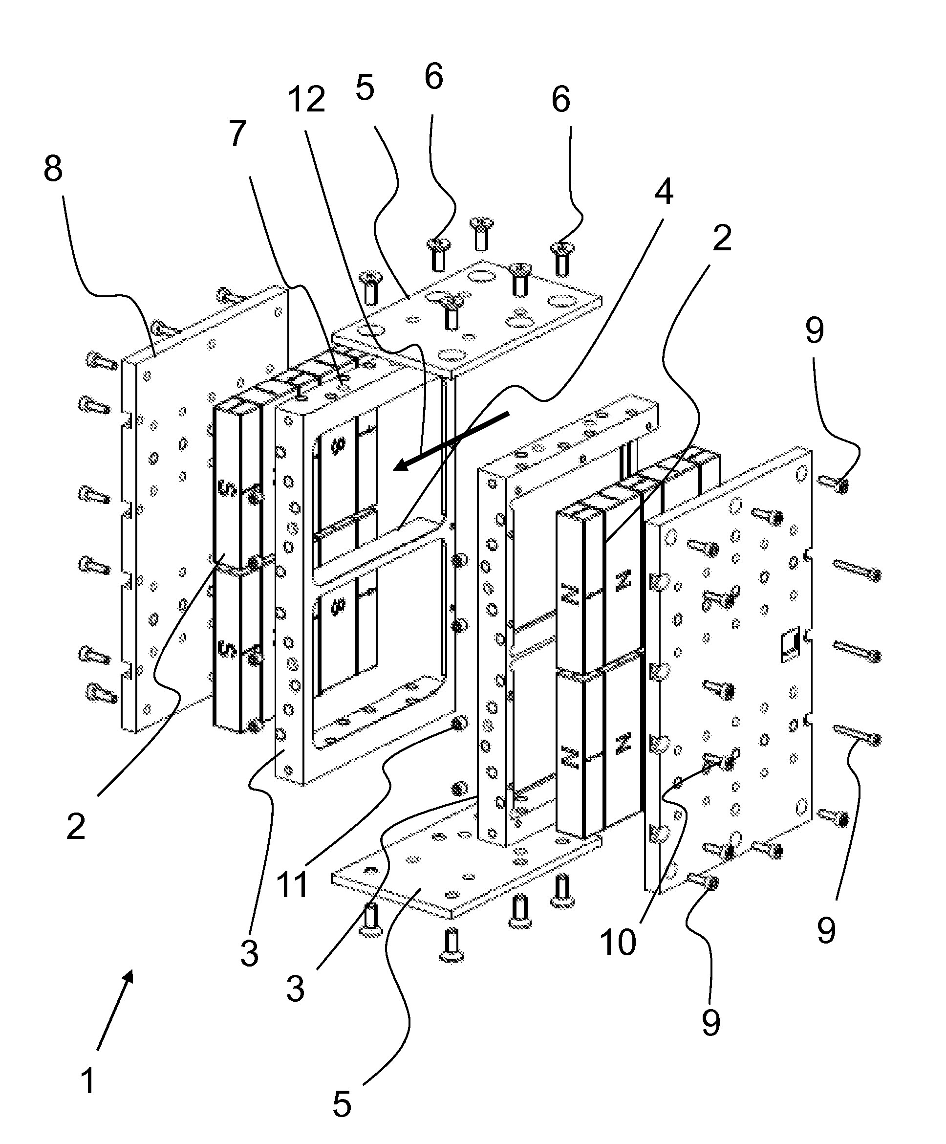
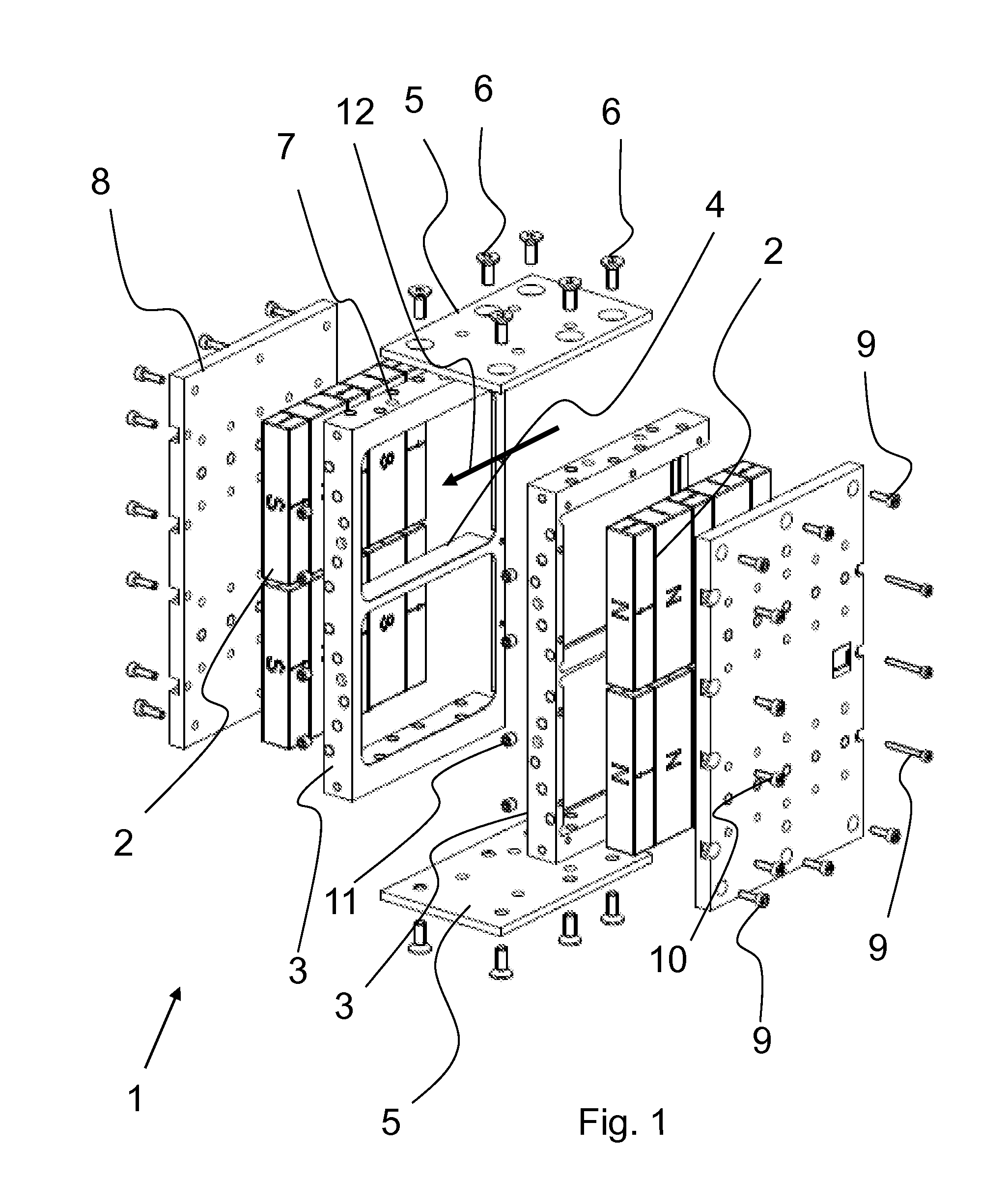
[0038]FIG. 1 shows an exploded view of a magnetic actor 1, and wherein in this depiction the coil and the housing have been omitted.

[0039]The magnetic actor 1 comprises two lateral parts that consist of the slide-in frame 3, permanent magnets 2 and the immobilization plate 8 respectively.

[0040]The slide-in frame 3, which is, for example, milled of non-ferromagnetic stainless steel, serves for the insertion of the magnets 2 that are arranged in a Halbach configuration. The direction of the slide-in insertion is marked by the arrow 12. During the installation the permanent magnets 2 can be pushed, on after the other, into the slide-in frame 3. For this end, the slide-in frame is open only on the insertion side in such a manner as to allow for the possibility of sliding the magnets into the fame. The slide-in frame 3 prevents that the magnets 2, which are arranged in different magnetization directions respectively, become distorted relative to each other. Two rows of magnets are arrang...


PUM

PropertyMeasurementUnit
forceaaaaaaaaaa
forcesaaaaaaaaaa
magnetizationaaaaaaaaaa

Abstract

The invention relates to a magnetic actor in which the permanent magnets are arranged in a Halbach configuration and inserted into a slide-in frame.

Description

CROSS-REFERENCE TO RELATED APPLICATIONS[0001]German patent application DE 10 2010 004 642.6, filed Jan. 13, 2010, is incorporated herein by reference.FIELD OF THE INVENTION[0002]The invention relates to a magnetic actor and to a method for its installation. In particular, the invention relates to a magnetic actor that is configured as a force actor for the active vibration isolation in the context of a vibration isolation system in the semiconductor technology.BACKGROUND OF THE INVENTION[0003]Magnetic actors are known in the art. They are a type of linear motor comprising a coil that is disposed between permanent magnets. When using such a magnetic actor for active vibration isolation, a part of the magnetic actor, for example the coil on the load that is to be isolated, and the other part, for example the permanent magnets, are fastened to the base. By triggering the coil it is possible to generate a force at least in one direction via the magnetic actor. This way, the magnetic act...

Claims


Application Information

Patent Timeline
Patent Type & Authority Applications(United States)
IPC IPC(8): H02K41/035H02K15/03
CPCH01F7/127H01F7/066F16F15/023H01F7/0221F16F15/03Y10T29/49009
Inventor EVERS, ARNDTTILLMANN, RALF
Owner INTEGRATED DYNAMICS ENG
Why Eureka
Try Eureka