Liquid ejecting apparatus

a technology of liquid ejecting apparatus and liquid, which is applied in the direction of printing, etc., can solve the problems of deteriorating liquid quality, affecting the effect of liquid quality, and introducing negative pressure into the closed space relatively short,

Inactive Publication Date: 2011-07-14
SEIKO EPSON CORP
View PDF4 Cites 7 Cited by
  • Summary
  • Abstract
  • Description
  • Claims
  • Application Information

AI Technical Summary

Benefits of technology

[0015]Therefore, since the negative pressure path opening in conjunction with the operation making the pressing force of the cap increases, simply by performing an operation for changing the pressing force, and the opened and closed states of the opening / closing portion can be changed appropriately. Thus, for example, though a plurality of caps is installed, a control in which the negative pressure is introduced into only the cap that is pressed by a high pressing force in a state where the negative pressure is not introduced with respect to the cap that is pressed by a small pressing force can be achieved simply.

Problems solved by technology

However, when the quality of the liquid is deteriorated, the deteriorated liquid is suctioned from the ejecting nozzle through operating a suction pump that is connected to a cap, which is in a state where the ejecting nozzle is covered by the cap.
However, in the above described related art, because the cap is pressed to the nozzle surface with strong force to prevent the leakage of the negative pressure, the cap is collapsed, and thus the negative pressure is likely to leak.
Further, while the capping portion abuts to the ejecting head, a time that the negative pressure is introduced into the closed space is relatively short, and almost all the remaining time, the capping portion is only made to abut solely to the ejection head.

Method used


Image

  • Liquid ejecting apparatus
  • Liquid ejecting apparatus
  • Liquid ejecting apparatus

Examples


first modification

C-1. First Modification

C-2. Second Modification

C-3. Third Modification

C-4. Fourth Modification

A. Construction of the Liquid Ejecting Apparatus

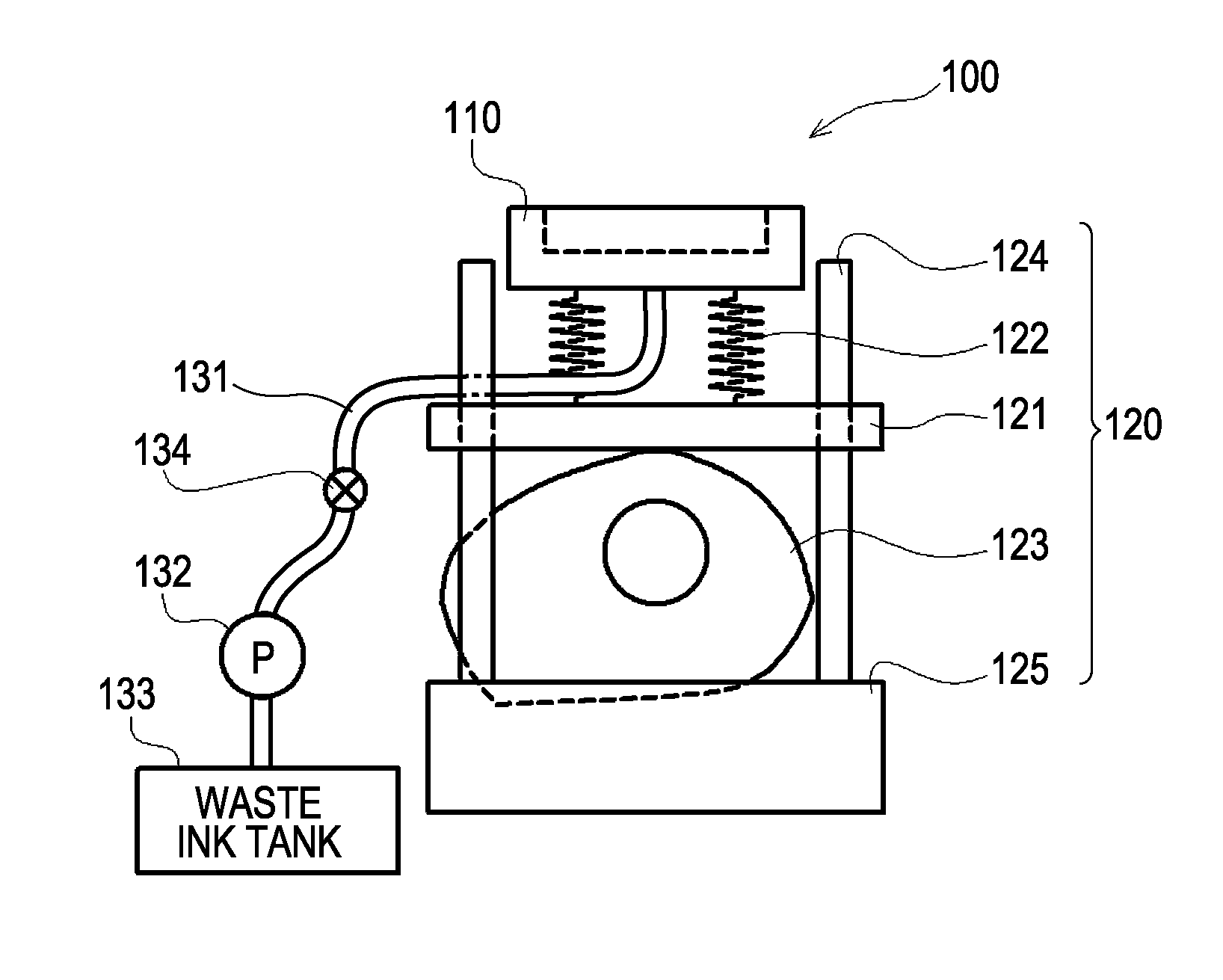
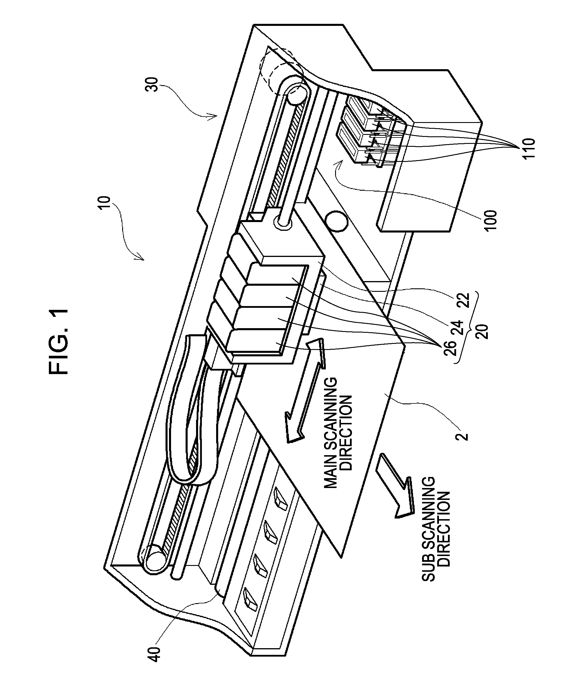
[0030]FIG. 1 is an explanatory view of the schematic construction of a liquid ejecting apparatus of the embodiment using so-called ink jet printer as an example. As illustrated FIG. 1, the ink jet printer 10 includes: a carriage 20 that forms an ink dot on a printing medium 2 while reciprocating in a main scanning direction, a driving unit 30 that reciprocates the carriage 20, and a paper feed roller 40 that feeds the printing medium 2, and the like. Also, in non-printing area (sometimes called “home position”) positioned at the ends of an area in which the carriage 20 is driven along with the main-scanning, a maintenance mechanism 100 is disposed to maintain the printer in order to appropriately perform ejection of the ink.

[0031]The carriage 20 includes: an ink cartridge 26 that receives black ink, cyan ink, magenta ink, and yellow ink, respe...

third modification

C-3. Third Modification

[0062]In the above described lifting units 120 of the embodiment, the first modification, and the second modification, the substrate plate 121 is lifted and the spring 122 is compressed after the cap 110 abuts to the nozzle surface of the ejecting head 24, thus, the pressing force of the cap 110 is increased. However, from adapting of a lifting unit described below, it is further possible that the pressing force is changed immediately after the cap 110 abuts to the nozzle surface.

[0063]FIG. 8 is an explanatory view illustrating a lifting unit of the third modification. As shown in FIG. 8, the third modification of the lifting unit largely consists of an upper unit 150 and a lower unit 160. The upper unit 150 includes a first cam shaft 152 which can switch the position of the substrate plate 121 to two steps of a high step and a low step, the cap 110, the spring 122, the substrate plate 121, and a box-type member 154 for receiving the first cam shaft 152. An up...

fourth modification

C-4. Fourth Modification

[0069]In the embodiment, the first modification, the second modification, and the third modification as described above, it is explained that the lifting unit 120, which makes the pressing force of the cap 110 about the ejecting head 24 changeable, is applied to so-called the ink jet print 10 having a single head. However, the lifting unit 120 can be applied to an ink jet printer (so-called line printer) in which a plurality of ejecting heads 24 is disposed in parallel.

[0070]FIG. 10 is an explanatory view illustrating a lifting unit 120 of the fourth modification applied to the line printer. Also, FIG. 10 illustrates the aspect of a printing area of the line printer (ink jet printer 10) of the fourth modification when viewing from above thereof. As shown in FIG. 10, in the fourth modification of the line printer, six-ejecting heads 24, which are rectangular approximately in shape, are installed along with the direction orthogonal to the transporting direction...


PUM


Abstract

When a negative pressure is introduced into a closed space formed by a cap abutting to an ejecting head, the cap abuts to the ejecting head with a greater pressing force than that in a case where the negative pressure is not introduced into the closed space. Therefore, the cap can abut to the ejecting head with a weak pressing force during the time when the negative pressure is not introduced, it can be avoided that the cap abuts to the ejecting head with a significant pressing force over a long time, and collapse of the cap can be significantly suppressed.

Description

BACKGROUND[0001]1. Technical Field[0002]The present invention relates to a liquid ejecting apparatus for ejecting a liquid from a liquid ejecting head.[0003]2. Related Art[0004]Generally, an ink jet printer provides a high quality image printing by ejecting a correct quantity of ink out of a fine ejecting nozzle to a correct position. Further, by using the ejecting technology, electrodes, sensors and bio-chips, and the like can be manufactured by ejecting various liquids instead of the ink to a substrate.[0005]In the ejection technology, during the time when the liquid is not ejected, deterioration of the quality of the liquid through evaporation or volatilization of its components can be suppressed through capping the ejecting nozzle. However, when the quality of the liquid is deteriorated, the deteriorated liquid is suctioned from the ejecting nozzle through operating a suction pump that is connected to a cap, which is in a state where the ejecting nozzle is covered by the cap.[00...

Claims


Application Information

Patent Timeline
Patent Type & Authority Applications(United States)
IPC IPC(8): B41J2/165
CPCB41J2/17596B41J2/16511
Inventor HARA, KEIJI
Owner SEIKO EPSON CORP
Why Eureka
Try Eureka