High intensity fabry-perot sensor

a technology of fabry-perot and sensor, applied in the field of high intensity fa, can solve problems such as the compromise of fabry-perot interferometer-based sensors, and achieve the effect of maximizing the reflected light signal

Active Publication Date: 2011-07-14
HALLIBURTON ENERGY SERVICES INC
View PDF11 Cites 15 Cited by
  • Summary
  • Abstract
  • Description
  • Claims
  • Application Information

AI Technical Summary

Benefits of technology

[0011]FIG. 2 is a concept drawing of sensor assembly with ball lens and Fabry-Perot gap, wherein the two surfaces of the window are plane parallel (where one

Problems solved by technology

As a result, if insufficient light reflected from the sensor re-enters the fibe

Method used


Image

  • High intensity fabry-perot sensor
  • High intensity fabry-perot sensor
  • High intensity fabry-perot sensor

Examples


Embodiment Construction

[0021]While the present invention is described with reference to the embodiments described herein, it should be clear that the present invention should not be limited to such embodiments. Therefore, the description of the embodiments herein is illustrative of the present invention and should not limit the scope of the invention as claimed.

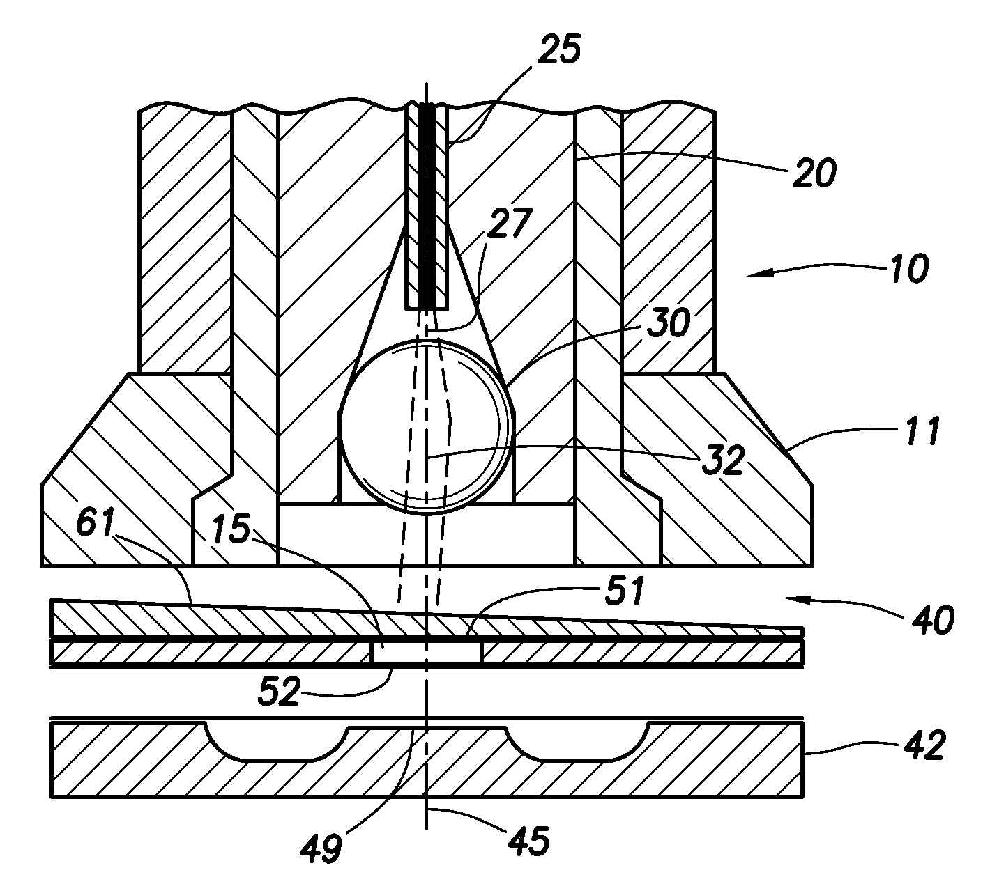
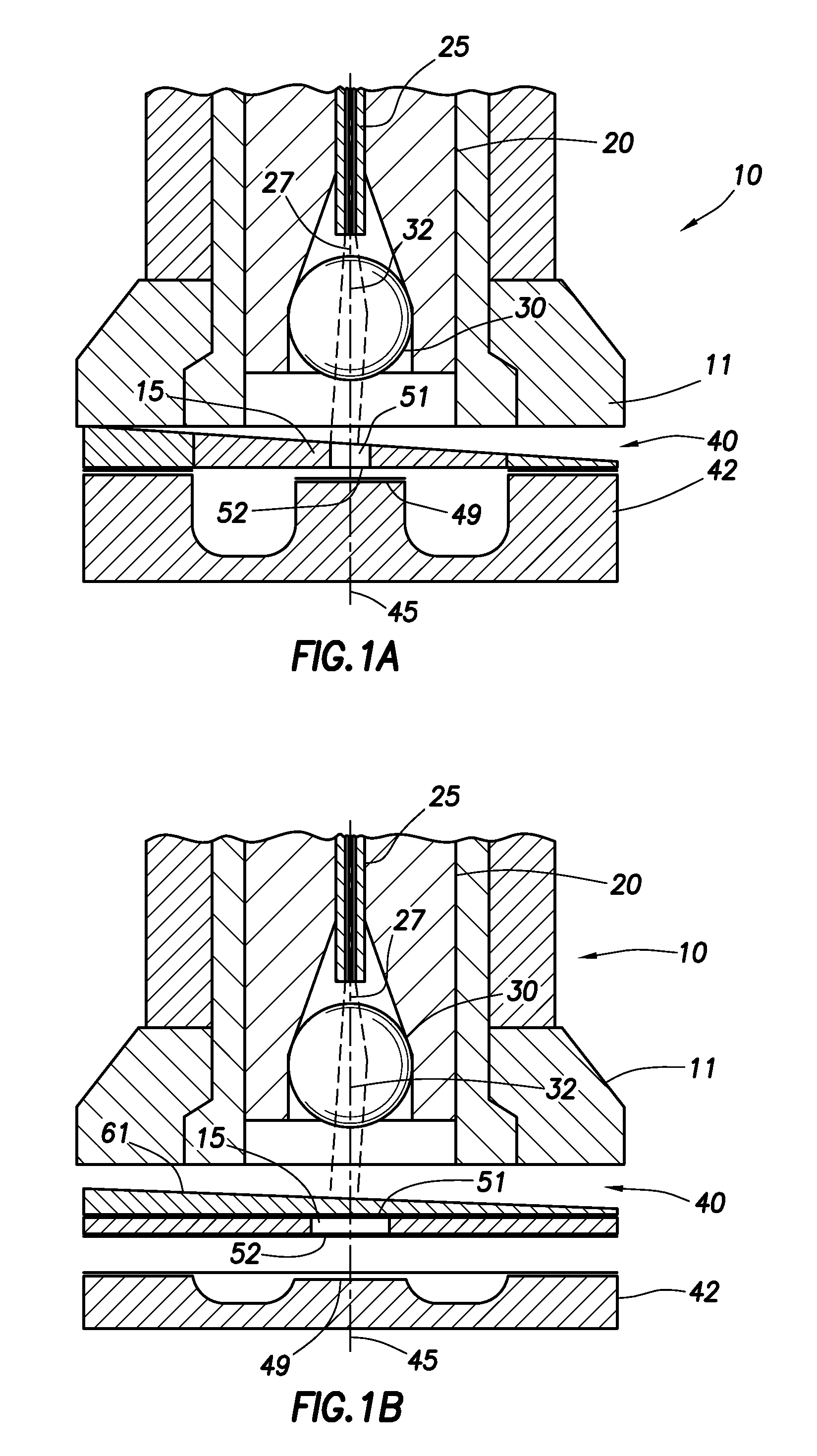
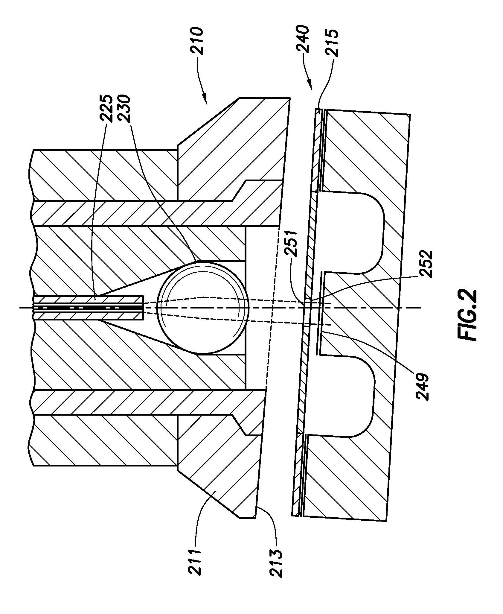
[0022]To obtain the maximum light intensity using a Fabry-Perot interferometer based sensor, it is necessary to assure the optical fiber is precisely centered on the lens optical axis and the second reflector in the Fabry-Perot interferometer is precisely perpendicular to the beam of light transmitted from the lens. Since these conditions cannot be met precisely in manufacturing practice, certain adjustments are necessary to achieve these results. An embodiment of a Fabry-Perot interferometer based sensor 10 is shown in FIG. 1A. In this embodiment, a wedge shaped window assembly 15 is used rather than a plane-parallel window as an alignment device....


PUM


Abstract

A sensor assembly having an optical fiber, a lens in optical communication with the optical fiber, a reflective surface spaced from the lens, for reflecting light from the beam back to the lens, a partially reflective surface positioned between the reflective surface and the lens, the partially reflective surface for reflecting light from the beam back to the lens, and an alignment device for aligning the lens and reflective surface with respect to one another, such that light from the beam of light transmitted from the lens reflects from the reflective surface back to the lens. The alignment device can have a rotational component and a base component, where the rotational component rotates to align a beam of light transmitted from the lens. The rotational component can also cooperate with the base component to move axially with respect to the reflective surfaces to align the beam for optimum power.

Description

CROSS-REFERENCE TO RELATED APPLICATIONS[0001]This application is a Continuation In Part of U.S. patent application Ser. No. 12 / 365,700 to Gibler et al. filed on Feb. 4, 2009 which was a continuation of U.S. patent application Ser. No. 11 / 377,050 to Gibler et al. filed on Mar. 16, 2006. This application claims priority from U.S. Provisional Patent Application No. 60 / 662,202 filed on Mar. 16, 2005, which is hereby incorporated by reference, and claims priority from U.S. Provisional Patent Application No. 60 / 774,289 filed on Feb. 17, 2006, which is also hereby incorporated by reference.FIELD OF INVENTION[0002]The present invention relates to sensors for measuring the absolute length of a gap in a Fabry-Perot interferometer, and more particularly to a Fabry-Perot sensor that provides a more intense signal.BACKGROUND OF THE INVENTION[0003]The use of Fabry-Perot interferometers to measure the absolute length of a gap is known. Use of a ball lens to collimate light shining on a Fabry-Perot...

Claims


Application Information

Patent Timeline
IPC IPC(8): G01B9/02
CPCG01B9/02G01J3/02G02B6/322G01J3/0289G01J3/26G01J3/0278G01B9/02056
Inventor GIBLER, WILLIAM N.JEFFERS, LARRY A.LOPUSHANSKY, RICHARD L.GILLHAM, FREDERICK J.LEBLANC, MICHEL
Owner HALLIBURTON ENERGY SERVICES INC
Why Eureka
Try Eureka