Method for Determining Random Access Channel Number and Sending Sounding Reference Signal

a random access channel and random access technology, applied in the field of communication, can solve problems such as large system overhead

Active Publication Date: 2011-07-14
ADVANCED STANDARD COMM LLC
View PDF5 Cites 8 Cited by
  • Summary
  • Abstract
  • Description
  • Claims
  • Application Information

AI Technical Summary

Benefits of technology

[0031]Using the above-described method allows the number of the PRACHs in the UpPTS in which the SRS is located to be calculated accur

Problems solved by technology

This method needs to store such a table in both the base st

Method used


Image

  • Method for Determining Random Access Channel Number and Sending Sounding Reference Signal
  • Method for Determining Random Access Channel Number and Sending Sounding Reference Signal
  • Method for Determining Random Access Channel Number and Sending Sounding Reference Signal

Examples


example 1

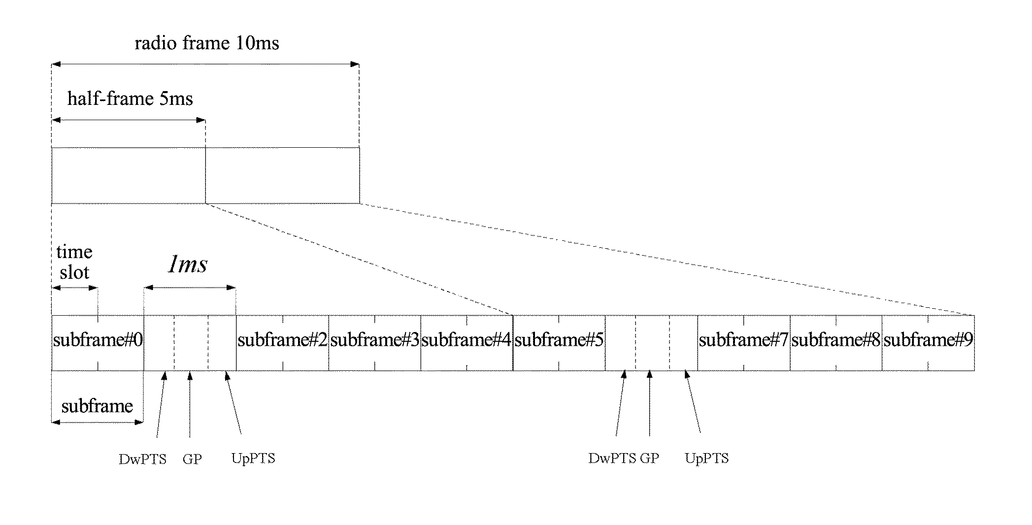
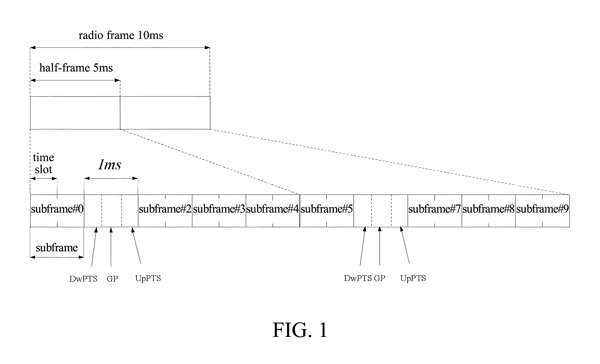
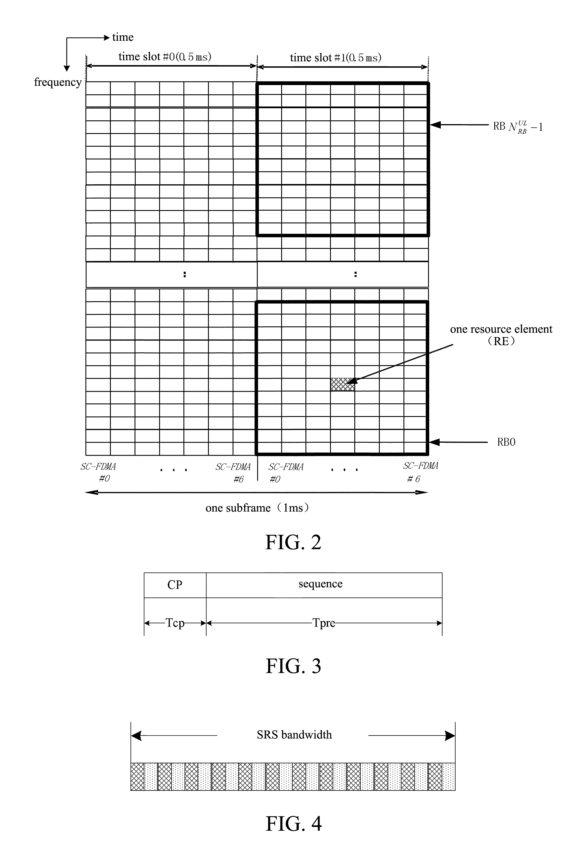
[0050]Assuming that the configured PRACH configuration index is 48 and uplink-to-downlink proportion configuration is 0, then NSP=2, as shown in FIG. 1, and DRA=0.5 and rRA=0, as shown in FIG. 3. Therefore, it can be seen from the present invention that there is one PRACH in an UpPTS in the first half-frame of a radio frame with a even system number, i.e., NRA=1, and there is no PRACH in other UpPTSs, i.e., NRA=0.

example 2

[0051]Assuming that the configured PRACH configuration index is 56 and uplink-to-downlink proportion configuration is 0, then NSP=2, as shown in FIG. 1, and DRA=5 and rRA=0, as shown in FIG. 3. Therefore, it can be seen from the present invention that there are 3 PRACHs in an UpPTS in the first half-frame of each radio frame, i.e., NRA=3, and there are 2 PRACHs in the UpPTS in the second half-frame of each radio frame, i.e., NRA=2.

[0052]The above description is merely the preferred embodiments of the present invention and is not intended to limit the invention. Various modifications and variations may be made by those skilled in the art. Any modification, equivalent substitution or improvement within the spirit and principle of the invention should be included in the scope of the appended claims of the invention.


PUM


Abstract

The present invention provides a method for determining the number of random access channels which is applied to a time division duplex system. The method comprises: a terminal determining configuration parameters related to the number of the random access channels in an UpPTS based on system configuration, said configuration parameters including the number of downlink-to-uplink switch-points in one radio frame NSP, the density of PRACHs in a random access configuration DRA, a system frame number of a system frame in which said UpPTS is located nf, and a version index corresponding to a PRACH configuration index rRA; and said terminal then calculating directly the number of the PRACHs in said UpPTS based on the configuration parameters. The present invention also provides a method for sending a SRS of a time division duplex system using the method for determining the number of the random access channels.

Description

TECHNICAL FIELD[0001]The present invention relates to communication field, and more particularly, to a method for determining the number of random access channels and a method for sending a sounding reference signal.TECHNICAL BACKGROUND[0002]FIG. 1 illustrates a schematic diagram of a frame structure in a TDD (Time Division Duplex) mode of a LTE system, which is also called frame structure type 2. In this type of frame structure, a radio frame of 10 ms (307200 Ts, 1 ms=30720 Ts) is divided into two half-frames, each having a length of 5 ms (153600 Ts) and containing 5 subframes with the length of 1 ms. The role of each of the subframes is shown in Table 1, where D represents a downlink subframe used for transmitting downlink signals, and U represents an uplink subframe (which is called generic uplink subframe) used for transmitting uplink signals. Furthermore, an uplink / downlink subframe is divided into 2 time slots of 0.5 ms, and S represents a special subframe which contains three...

Claims


Application Information

Patent Timeline
IPC IPC(8): H04J3/00H04W72/04
CPCH04W74/0833H04W74/002
Inventor HAO, PENGDAI, BOLIANG, CHUNLIYU, BIN
Owner ADVANCED STANDARD COMM LLC
Why Eureka
Try Eureka