Multi-stage reciprocating compressor

a compressor and multi-stage technology, applied in the direction of pump components, positive displacement liquid engines, liquid fuel engine components, etc., can solve the problems of increased size and overall weight of external piping, increased vibration and high and low frequency noise, and increased internal piping. the effect of reducing the number of joints

Inactive Publication Date: 2011-07-14
CARRIER CORP
View PDF10 Cites 48 Cited by
  • Summary
  • Abstract
  • Description
  • Claims
  • Application Information

AI Technical Summary

Problems solved by technology

Unfortunately, the external tubing or piping can be a source of vibration and high and low frequency noise.
The external piping also increases the size and overall weight of the compressor.
The external piping also creates extra joints which have the potential to leak and adds additional parts which necessitate additional manufacturing steps including the fitting of piping to the compressor casing.

Method used


Image

  • Multi-stage reciprocating compressor
  • Multi-stage reciprocating compressor
  • Multi-stage reciprocating compressor

Examples


Embodiment Construction

Overview of the Compressor 10

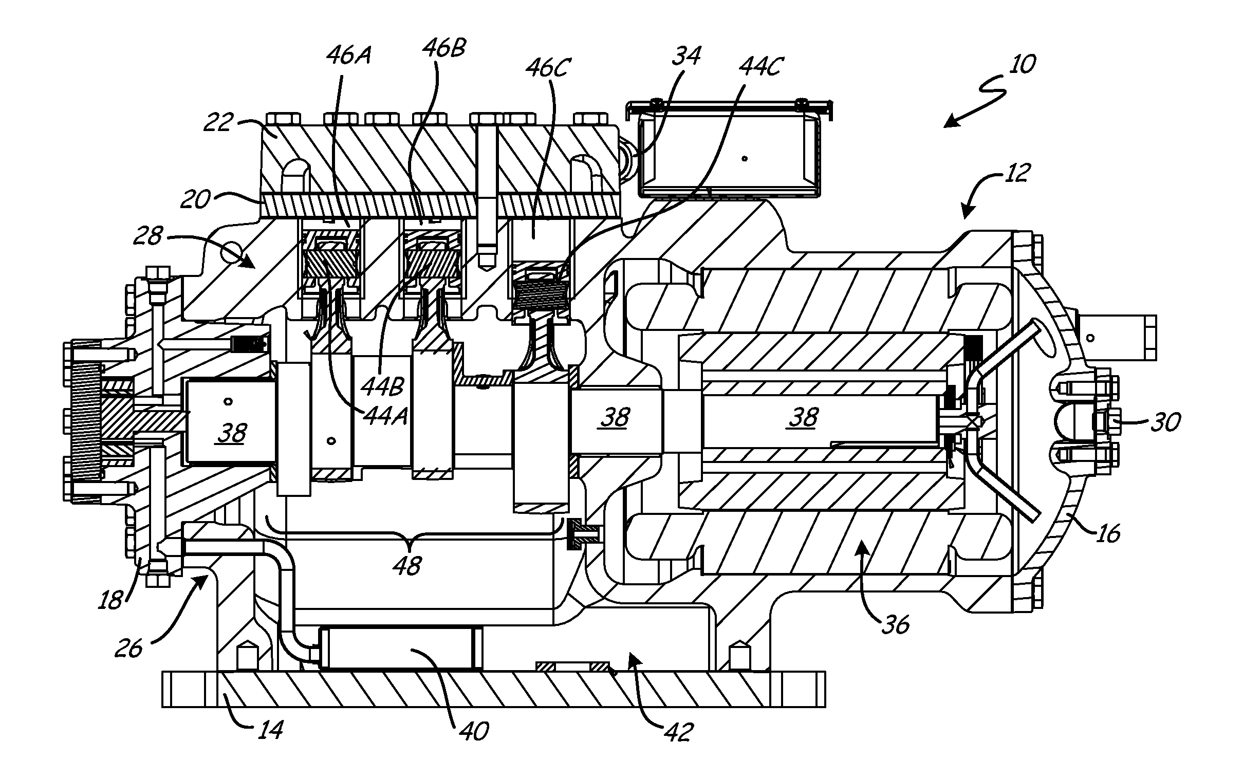
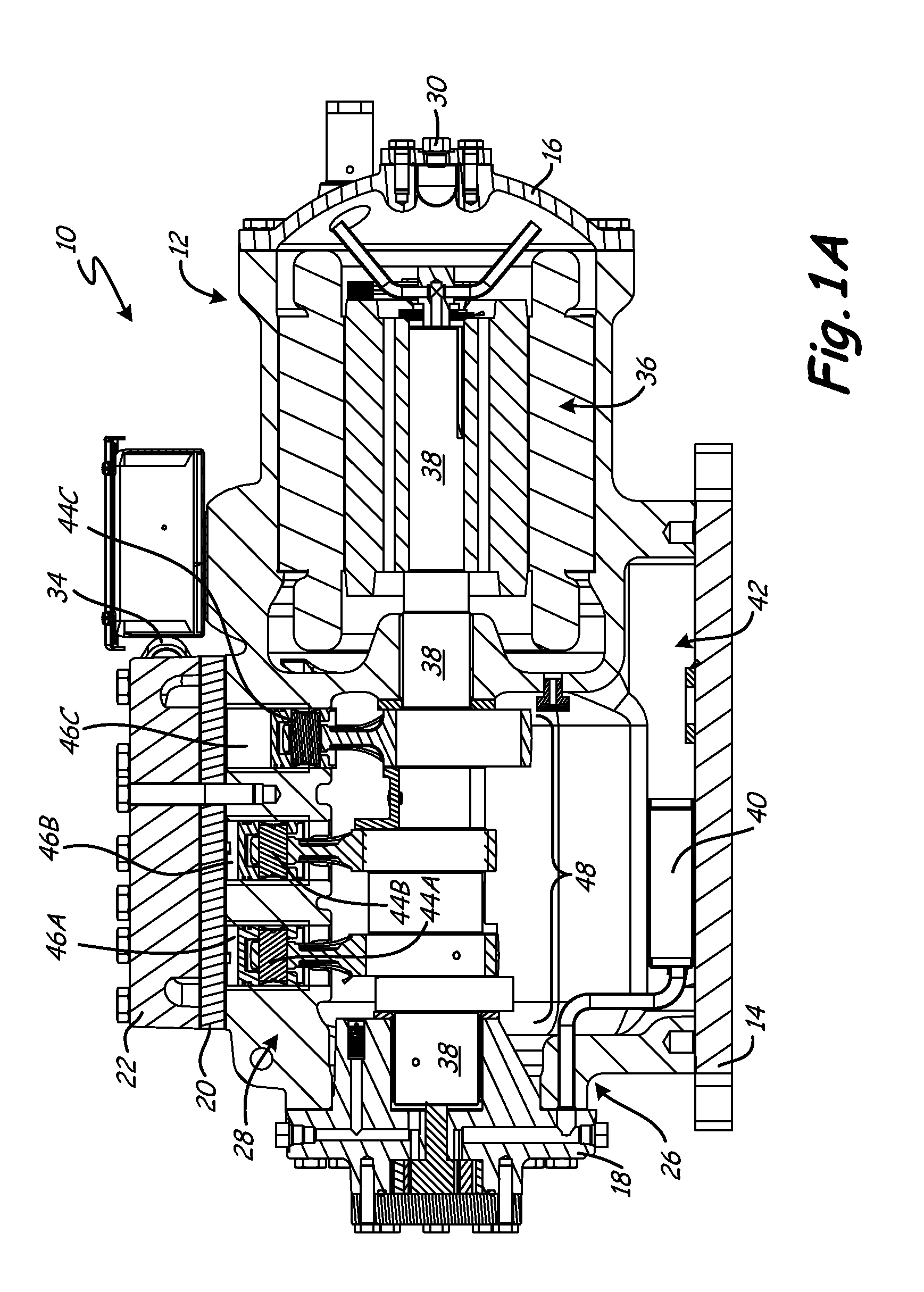
FIG. 1 shows a side view of one embodiment of a multi-stage reciprocating compressor 10. The reciprocating compressor 10 includes a casing 12, a mounting plate 14, a motor end cover 16, a bearing head assembly 18, a valve plate 20, and a cylinder head 22. The casing 12 includes a motor section 24, a crank case 26, and a cylinder block 28. The motor end cover 16 includes an inlet port 30. The cylinder block 28 includes a mid-stage port 32. The cylinder head 22 includes a high stage outlet port 34.

The compressor 10 includes the casing 12 which interconnects with the mounting plate 14. The casing 12 extends laterally from a first end, which receives the motor end cover 16, to a second end, which receives the bearing head assembly 18. The valve plate 20 and cylinder head 22 are secured to an upper portion of the casing 12. The motor section 24 of the casing 12 is overhung with respect to the mounting plate 14 and receives the motor end cover 16. The motor se...


PUM


Abstract

A multi-stage reciprocating compressor includes a cylinder block and a cylinder head. The cylinder block defines a low stage cylinder and a high stage cylinder. The cylinder head is secured to the cylinder block overlying the low and high stage cylinders. The cylinder head defines a mid-stage plenum which is in fluid communication with the low stage cylinder and the high stage cylinder for communicating a working fluid discharged from the low stage cylinder to the high stage cylinder.

Description

BACKGROUNDThe present invention relates generally to reciprocating compressor assemblies, and more particularly, to multi-stage compressors that have two or more cylinders.Compressors are used in many cooling, heating or refrigeration systems to compress a refrigerant fluid which circulates through the system. In the case of reciprocating compressors, a motor or engine turns a crankshaft which actuates reciprocation of one or more pistons inside one or more cylinders. Low pressure refrigerant enters the compressor through an inlet port in the compressor's casing and may be housed temporarily in a reservoir defined by the casing. The low pressure refrigerant from the reservoir is then drawn into the cylinders through a passageway(s) and compressed by the piston(s) to a higher temperature and pressure. The high pressure refrigerant gas discharged from the cylinder(s) leaves the reciprocating compressor through an outlet port in the cylinder head or casing and flows to the other compon...

Claims


Application Information

Patent Timeline
Patent Type & Authority Applications(United States)
IPC IPC(8): F04B25/00
CPCF04B53/16F04B53/104F04B53/162
Inventor FLANIGAN, PAUL J.
Owner CARRIER CORP
Why Eureka
Try Eureka