Dental bur

a bur and dental technology, applied in dentistry, dental tools, medical science, etc., can solve the problems of reducing cutting accuracy and performance, not necessarily preventing damage to the torque lock section,

Inactive Publication Date: 2011-07-14
TTI TURNER TECH INSTR
View PDF2 Cites 7 Cited by
  • Summary
  • Abstract
  • Description
  • Claims
  • Application Information

AI Technical Summary

Benefits of technology

[0007]It is an object of the present invention to obviate or mitigate at least one disadvantage of prior art bur designs.

Problems solved by technology

In particular, the present applicants have discovered that making the contact area available for torque transfer as large as possible, which would appear logical in order to avoid damage to the torque lock portion by angular forces, does not necessarily prevent damage to the torque lock section.
The present applicants have surprisingly discovered that damage to the torque lock portion can also be caused by vibration of the tool in the drive arrangement and that such vibrations can also reduce cutting accuracy and performance.

Method used


Image

  • Dental bur
  • Dental bur
  • Dental bur

Examples


Embodiment Construction

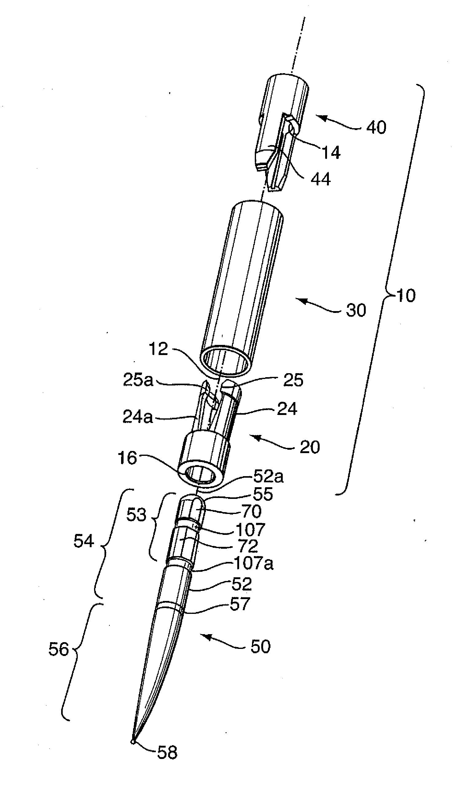
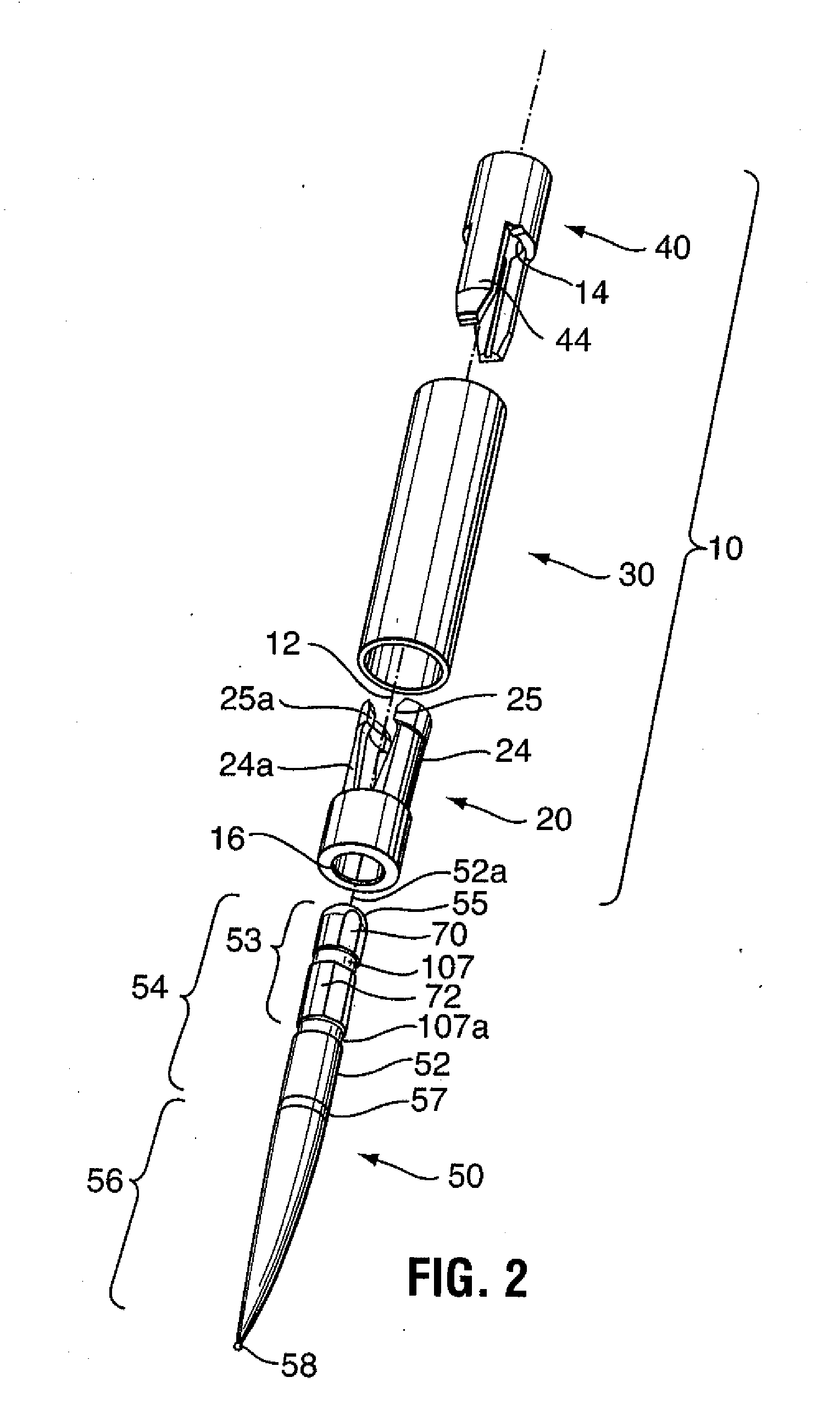
[0032]Generally, the present invention provides a bur for a dental or medical handpiece having a rotatable chuck with a tool bore for receiving the bur, a friction grip member for frictionally retaining the bur in the chuck and a torque lock seat of non-circular cross-section. As shown in FIGS. 3, 8 and 9, the bur has a tool body 52 having an axis of rotation 52a and is divided into a generally cylindrical, driven portion 54, with a driven end 55 for insertion into the chuck, and a working portion 56 for projecting from the drive head during use. At the driven end 55, the bur includes a non-round torque lock portion with alternating flat sections 70 cut into the cylindrical shaft of the bur and round sections 72 in which the exterior surface of the shaft remains intact. At least three flat sections 70 are preferably included.

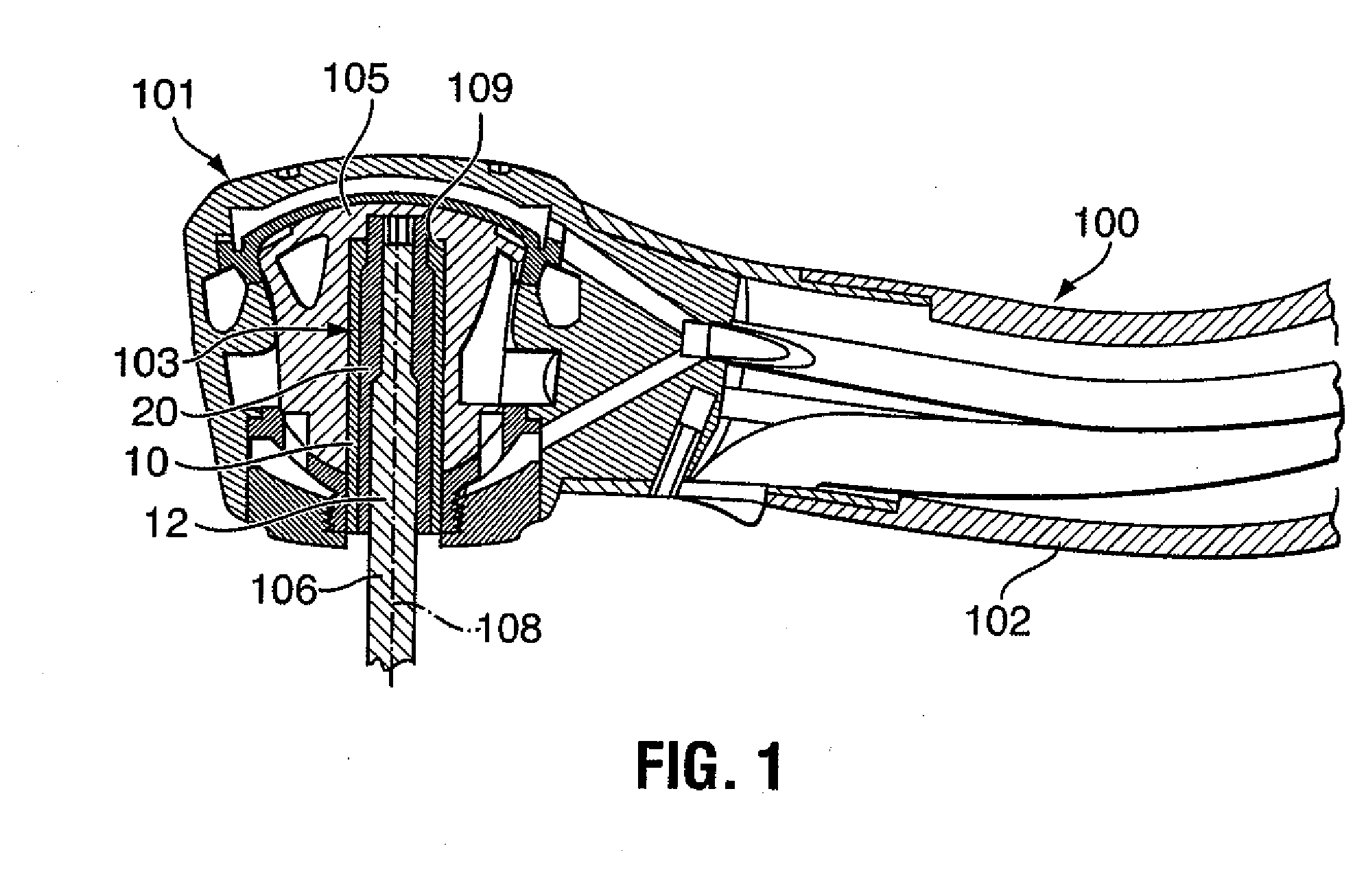
[0033]When the handpiece includes a bur drive arrangement permitting length adjustment of the bur in the drive head by concentrically supporting the bur in the ...


PUM


Abstract

The invention relates to an improved bur for use in handpieces having a rotatable chuck with a tool bore for receiving the bur, a friction grip member for frictionally retaining the bur in the chuck and a torque lock seat of non-circular cross-section and permitting length adjustment of the bur in the drive head by concentrically supporting the bur in the drive head at any position from a fully inserted position to a maximum retracted position. The bur includes a tool body having an axis of rotation, a working end for projecting from the handpiece and a driven end for insertion into the tool bore of the chuck. The driven end is a generally cylindrical shaft with a preselected outer circumference for fittingly engaging in the tool bore for concentric rotation of the driven end with the chuck. The shaft including a torque lock portion for fittingly and non-rotatably engaging the torque lock seat of the chuck. The torque lock portion has at least two flat surfaces circumferentially spaced apart by intermediate cylindrical mantle portions, for providing the locking portion with a cross-section including alternating circular and straight sections and fitting into the non-circular cross-section of the torque lock seat to prevent rotation of the torque lock portion in the torque lock seat. The circular sections have the same diameter as the outer diameter of the cylindrical shaft. A total area of the flat surfaces covers at least 0.001956 square inches and the circular sections extend over at least 30% of the outer circumference of the driven end. This maintains efficient torque transfer between the chuck and the tool and ensures concentricity of the bur in the handpiece to prevent undue vibration of the bur in the handpiece.

Description

CROSS-REFERENCE TO RELATED APPLICATION[0001]This application claims priority from U.S. Application Ser. No. 61 / 250,283, filed Oct. 9, 2009 and entitled Dental Bur, which application is included herein by reference in its entirety.FIELD OF THE INVENTION[0002]The present invention relates generally to dental and medical tools and in particular to dental burs.BACKGROUND OF THE INVENTION[0003]Numerous medical and dental handpieces for rotating tools exist. Turbine driven handpieces are widely used in dental offices and medical labs around the world. Most handpieces include a handle and a drive head for supporting the rotating tool. The drive head houses a tool drive, generally composed of a tool retaining mount or chuck, and a motor or turbine, rotatably mounted in the head for driving the chuck. The chuck releasably holds the tool, such as a dental bur, for rotation about an axis of rotation. The tool is releasably held by the chuck against axial movement in the drive arrangement. Vari...

Claims


Application Information

Patent Timeline
Patent Type & Authority Applications(United States)
IPC IPC(8): A61C3/00
CPCA61C1/08A61C3/02A61C1/14
Inventor TURNER, DEREK M.J.BAILEY, KEVIN JOHN
Owner TTI TURNER TECH INSTR
Why Eureka
Try Eureka