
Thumb metacarpal implant

a technology of metacarpal implants and thumbs, applied in the field of thumb metacarpal implants, can solve the problems of design and manufacture of functional, durable, and robust joint prosthesis, and achieve the effect of facilitating hemi-arthroplasty and stabilizing joints

Active Publication Date: 2011-07-14
ASCENSION ORTHOPEDICS
View PDF8 Cites 10 Cited by
  • Summary
  • Abstract
  • Description
  • Claims
  • Application Information

AI Technical Summary

Benefits of technology

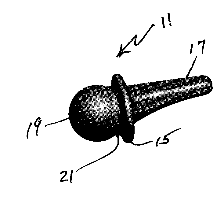
[0006]It has been found that a particularly stable joint, which will exhibit resistance to joint subluxion and dislocation, can be achieved through the combined effect of three design features of an implant to be employed in a procedure wherein an articulating surface is provided in the form of a spherical cavity by surgically adapting the trapezium to serve as a socket which receives the head of an implant that is seated in the resected end of the base of the thumb metacarpus. Although this basic concept has previously been employed, it has now been found to be truly effective in providing the full range of motion and stability as a result of the careful design of the head region of the implant that is seated in the base of the resected metacarpus. It has been found that, by capture of about one-third to one-half of the spherical region of a spherical head of an implant having a head region incorporating these three design features in combination, a significantly improved hemi-arthroplasty is facilitated. These features interrelate a head section that includes a head and a neck, together with a base collar, which interface with the trapezium during flexion and extension while allowing circumduction and axial rotation at the joint, and a medullary stem which is offset from the head section and collar which provides fixation of the implant to the metacarpus.

Problems solved by technology

Overall, the design and manufacture of a functional, robust, and durable joint prosthesis is a complex and multifaceted problem involving anatomical, biocompatibility, biomechanical, and surgical considerations.
Anatomical issues for consideration involve the shape of the intramedullary stem and of the articulating surface, and the need for a range of sizes to accommodate anthropomorphic variations.

Method used


Image

  • Thumb metacarpal implant
  • Thumb metacarpal implant
  • Thumb metacarpal implant

Examples


Embodiment Construction

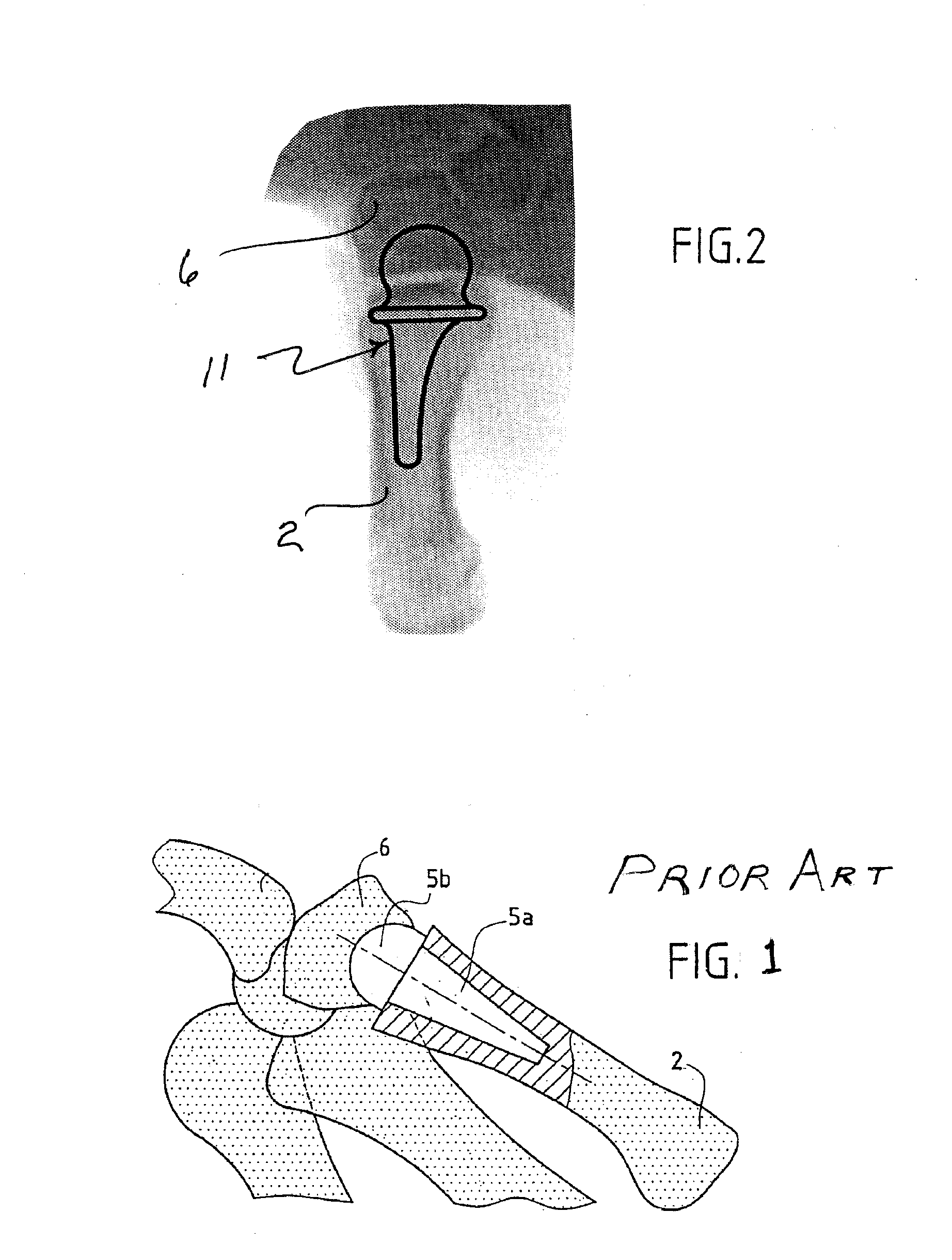
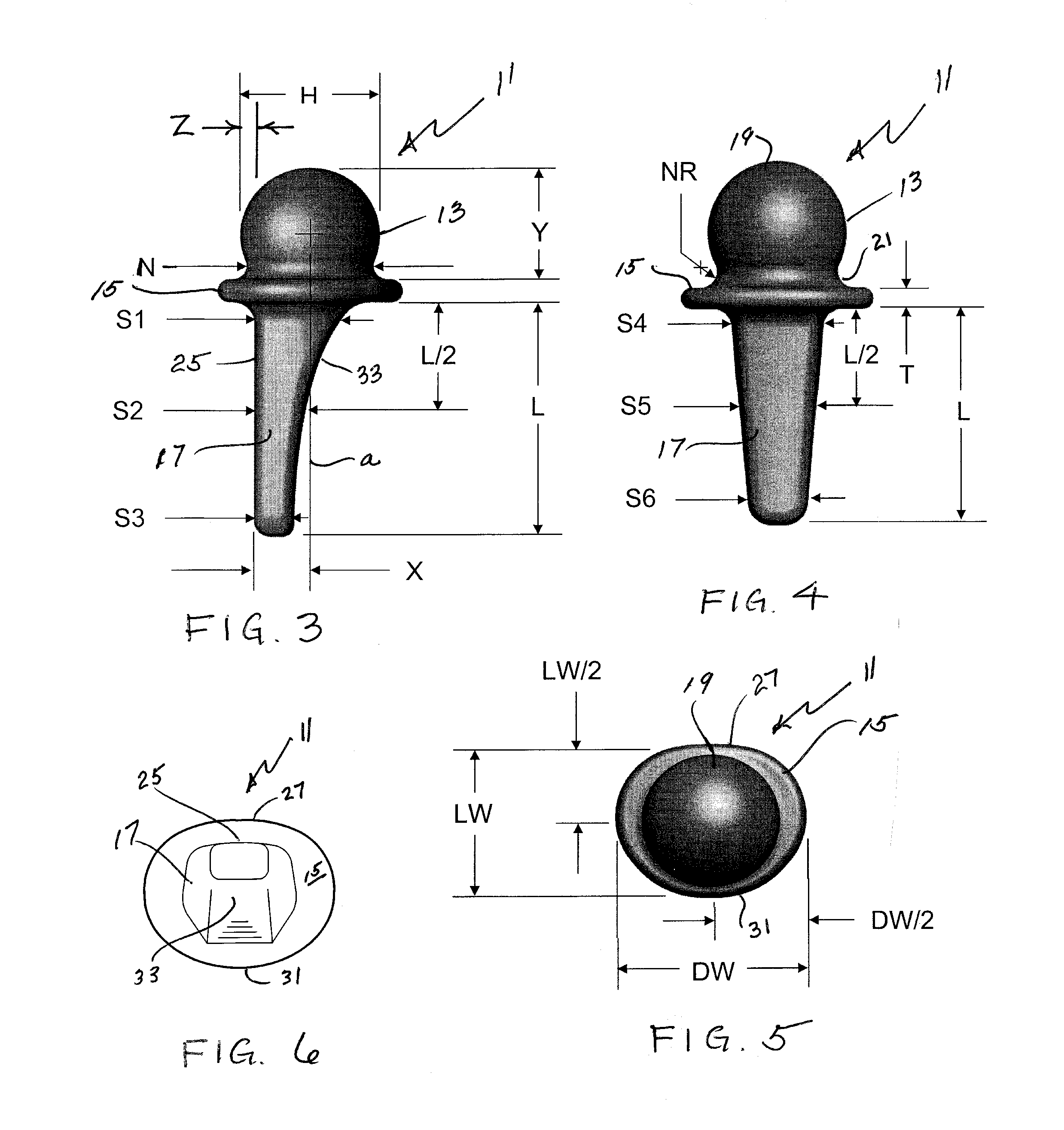
[0023]FIG. 1 illustrates a prosthesis made in accordance with the prior art having a stem 5a which is implanted in the resected proximal end of the metacarpus 2 and having a head 5b that is received in a surgically prepared cavity in the trapezium 6. FIG. 2 illustrates a prosthesis or implant 11 embodying features of the present invention shown similarly implanted for purpose of comparison.

[0024]As best seen in FIG. 3, one embodiment of the prosthesis 11 has a head section 13, a flat collar 15 which provides a base for the head section and a stem 17. The head section 13 includes a spherical articular head 19 which is connected by a neck 21 to the proximal surface of the flat collar 15; the intramedullary stem 17 extends from the rear or distal surface of the flat collar. The prosthesis 11 is designed to be implanted in the medullary canal of the first metacarpus 2 after removing the base of that bone. By providing the prosthesis 11 in four different sizes of heads and stems, it is e...


PUM

PropertyMeasurementUnit
Fractionaaaaaaaaaa
Fractionaaaaaaaaaa
Fractionaaaaaaaaaa

Abstract

A hemi-arthroplasty implant (11) joint replacement for the base of the first metacarpal of the CMC joint is created which can effectively restore and reestablish functional joint mechanics. The implant (11) has a unique head section (13) creating a particular interrelation between a spherical head articular surface (19), that is received in a surgically prepared cavity in the trapezium, wherein a supporting neck (21) in a re-entrant region joins the head to a flat, generally oblong collar (15).

Description

[0001]This application claims priority from U.S. Provisional Patent Application Ser. No. 61 / 097,597, filed Sep. 17, 2008.[0002]This invention relates to implants designed for the proximal end of the thumb metacarpus and, more particularly, to an implant for insertion into the resected proximal end of the thumb metacarpus, having a head that will articulate with a surgically prepared cavity in the trapezium to effect a hemi-arthroplasty of the thumb carpometacarpal (CMC) joint.BACKGROUND OF THE INVENTION[0003]Overall, the design and manufacture of a functional, robust, and durable joint prosthesis is a complex and multifaceted problem involving anatomical, biocompatibility, biomechanical, and surgical considerations. From a functional perspective, mechanical design considerations should address the joint range of motion, center of rotation, force-transmission-capabilities, and wear resistance of the component. Anatomical issues for consideration involve the shape of the intramedullar...

Claims


Application Information

Patent Timeline
IPC IPC(8): A61F2/42
CPCA61F2/4241A61F2002/30574A61F2310/00574A61F2002/30158A61F2310/00173A61F2002/4258
Inventor KLAWITTER, JEROME J.RITZ, JOSEPH P.GOURLEY, MONTI R.DEGROOD, ASHLEY
Owner ASCENSION ORTHOPEDICS
Learn More