

System of Testing Engineered Safety Feature Instruments
a technology of safety feature and engineered safety, which is applied in the field of testing engineered safety feature (esf) instruments, can solve the problems of human error, high cost, and complex system interface, and achieve the effects of saving human resources, improving testing speed, and saving costs
- Summary
- Abstract
- Description
- Claims
- Application Information
AI Technical Summary
Benefits of technology
Problems solved by technology
Method used
Image

Examples
Embodiment Construction
[0012]The following description of the preferred embodiment is provided to understand the features and the structures of the present invention.
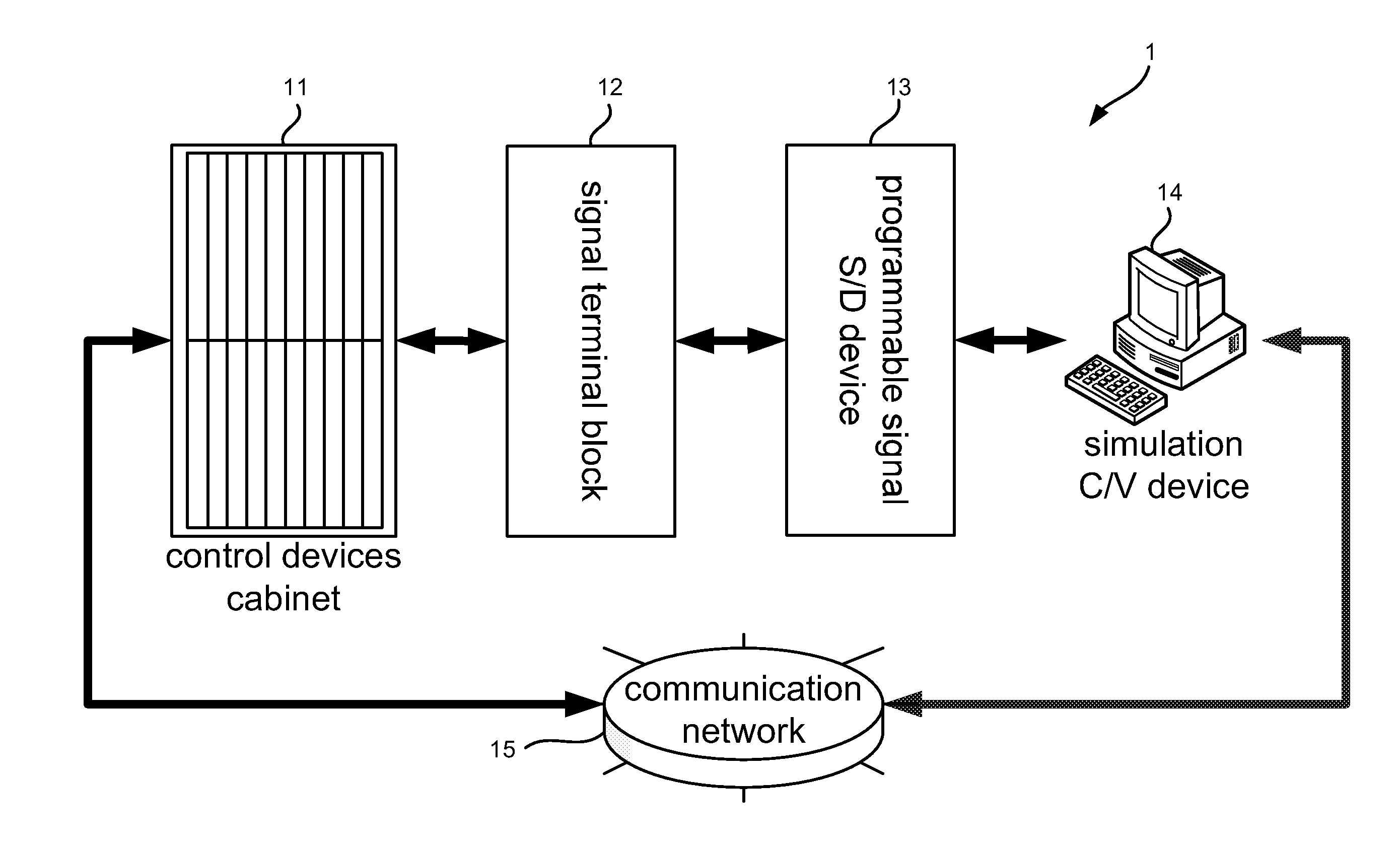
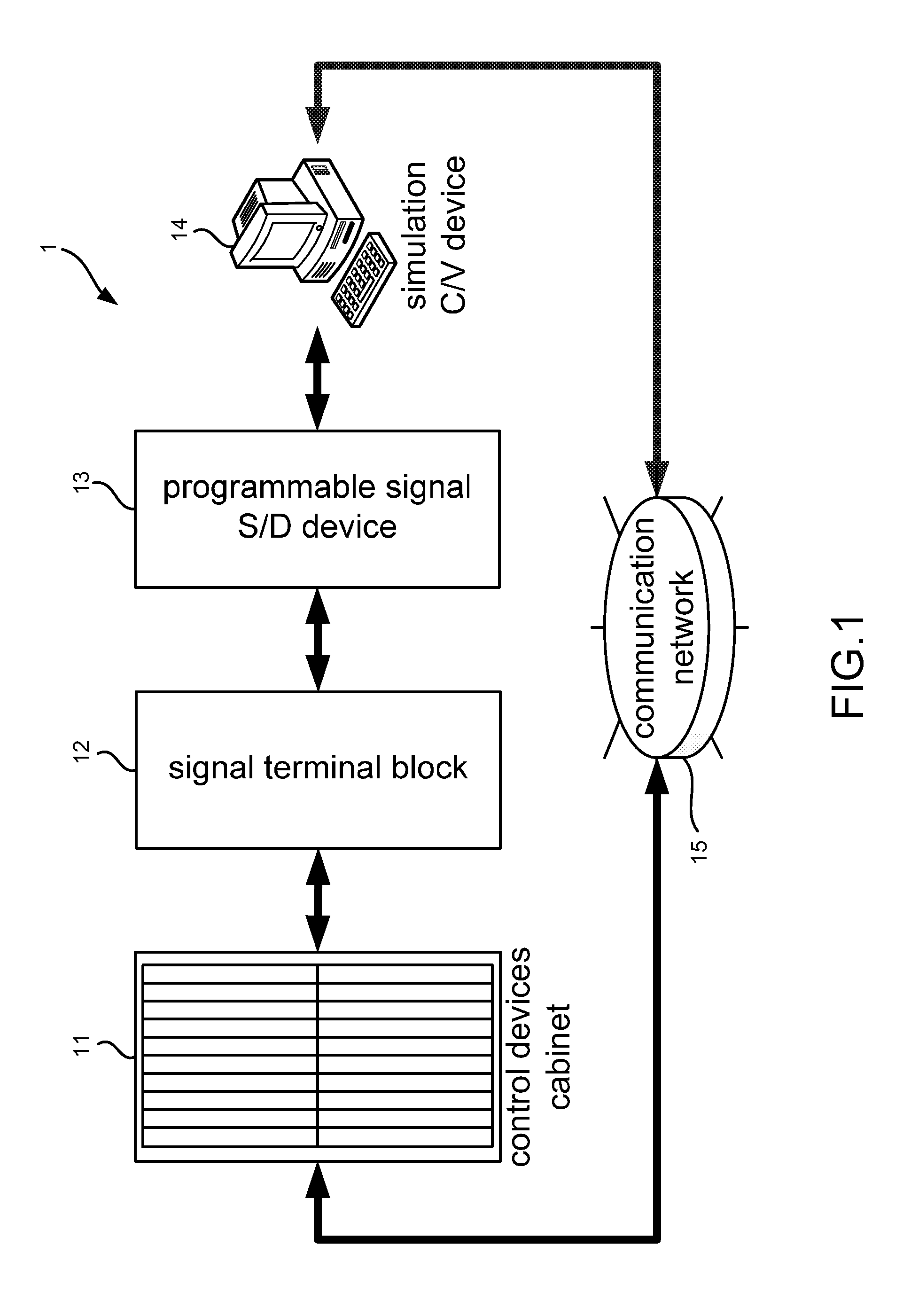
[0013]Please refer to FIG. 1, which is a structural view showing a preferred embodiment according to the present invention. As shown in the figure, the present invention is a system of testing engineered safety feature instruments, comprising a control devices cabinet 11, a signal terminal block 12, a programmable signal S / D device 13, a simulation C / V device 14 and a communication network 15, where a time for testing control modules is shortened with functions of the control modules verified.
[0014]The control devices cabinet 11 holds a plurality of engineered safety feature instruments; and comprises a communication module and a plurality of control modules. The communication module provides a communication interface between the control modules of the engineered safety feature instruments and the communication network 15. Each control module...
PUM
 Abstract
Description
Claims
Application Information