Wastewater treatment system and wastewater treatment process

a wastewater treatment and wastewater technology, applied in the direction of sedimentation settling tanks, other chemical processes, separation processes, etc., can solve the problems of system overload, system processing difficulty, and system overloading,

Inactive Publication Date: 2011-07-21
HITACHI PLANT TECH LTD
View PDF16 Cites 12 Cited by
  • Summary
  • Abstract
  • Description
  • Claims
  • Application Information

AI Technical Summary

Benefits of technology

[0018]The present invention can offer a wastewater treatment system and a wastewater treatment process to which an MBR is applied and which can respond to fluctuations in the quantity of water.

Problems solved by technology

The wastewater treatment system described in “Guidelines for Introduction of Membrane Treatment Technology into Sewage Systems” is incapable of responding to flow rates exceeding the filtering capacity of membranes when membrane separation is carried out in the reaction tanks 106.
However, it is possible that when the quantity of water reaches the peak due to heavy rain or the like, the system may be overloaded and have difficulty in the treatment.
The treatment is also expected to be difficult when membranes in the reaction tank 106 are clogged.
However, problems of these countermeasures are complicated operation management and high facility cost due to a larger membrane separation apparatus.
Thus, the application of MBR processes is difficult because of the failure to treat wastewater in the final sedimentation tank 108 when the quantity of water which flows into reaction tanks 106 exceeds the filtering capacity of an MBR.

Method used


Image

  • Wastewater treatment system and wastewater treatment process
  • Wastewater treatment system and wastewater treatment process
  • Wastewater treatment system and wastewater treatment process

Examples


Embodiment Construction

[0026]Hereinafter preferred embodiments of the present invention will be described with reference to the accompanying drawings. Although the present invention is described by the following preferred embodiments, the present invention may be modified by various techniques without departing from the scope of the present invention, and embodiments other than the present embodiments may be employed. Accordingly, all modifications within the scope of the present invention are included in the claims. The numerical ranges represented by “to” as used herein include numerical values written before and after “to”.

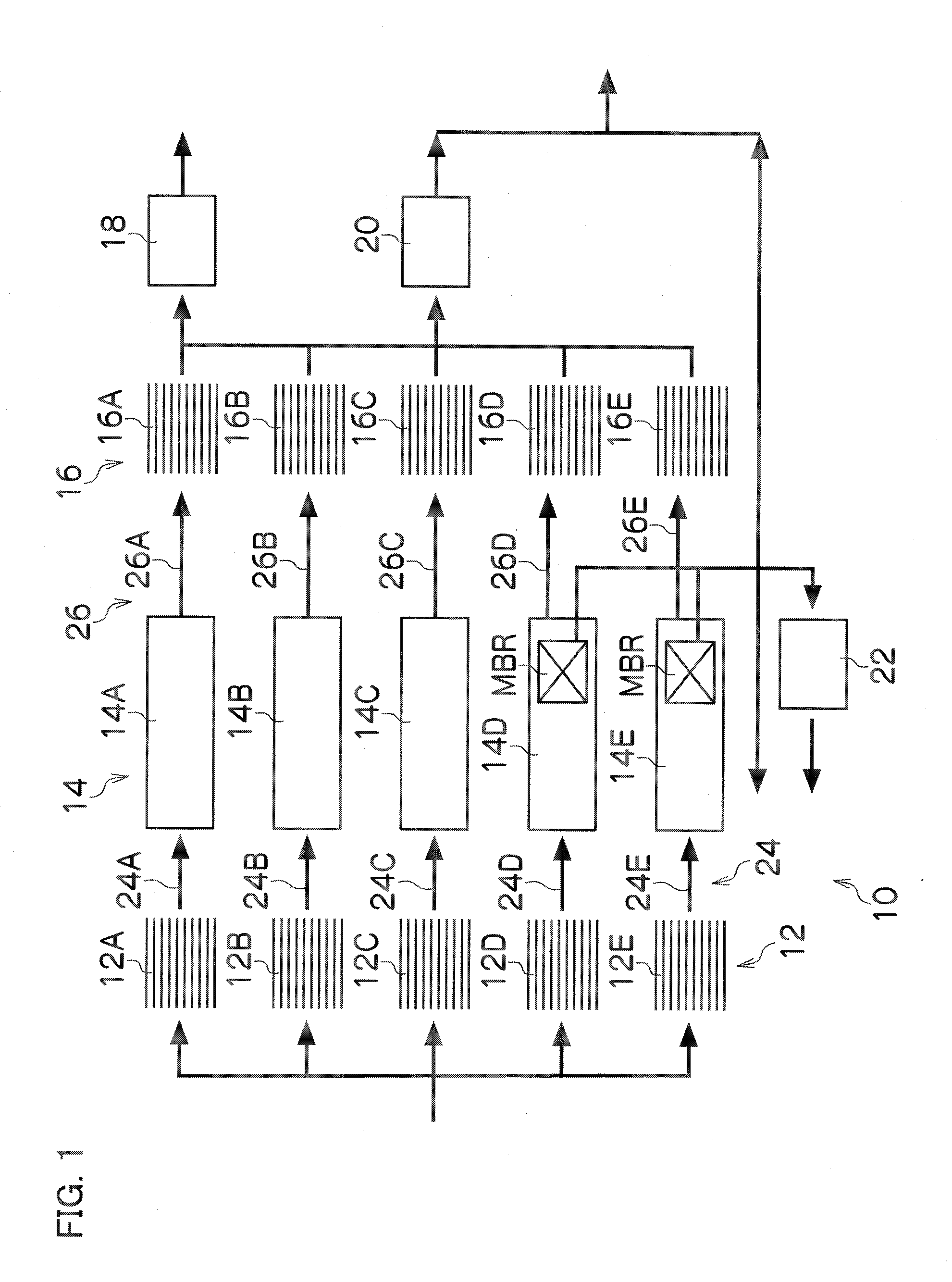
[0027]FIG. 1 is a schematic view illustrating the entire structure of a wastewater treatment apparatus according to the present embodiment. The wastewater treatment system 10 includes a plurality of first sedimentation tanks 12 (12A-12E), reaction tanks 14A-14C connected to first sedimentation tanks 12A-12C in which an activated-sludge process is performed, reaction tanks 14D and 14E...


PUM

PropertyMeasurementUnit
concentrationaaaaaaaaaa

Abstract

The wastewater treatment system according to the present invention includes a plurality of reaction sequences including a first sedimentation tank, a reaction tank, a final sedimentation tank, a first channel which connects the first sedimentation tank and the reaction tank and a second channel which connects the reaction tank and the final sedimentation tank. In one reaction sequence of the plurality of reaction sequences, the reaction tank has a membrane separation tank including a carrier, a membrane unit, and activated sludge and in which an MLSS concentration of the activated sludge is in a range of 500 mg/L to 7000 mg/L, and wastewater is supplied to the reaction tank via the first channel, and wastewater in a quantity exceeding a treatment capacity of the reaction tank is supplied to the final sedimentation tank via the second channel.

Description

BACKGROUND OF THE INVENTION[0001]1. Field of the Invention[0002]The present invention relates to a wastewater treatment system and a wastewater treatment process, and more particularly to a wastewater treatment system and a wastewater treatment process which use membrane separation.[0003]2. Description of the Related Art[0004]In the past wastewater treatment systems equipped with a first sedimentation tank, a reaction tank (biological treatment tank) and a final sedimentation tank have been known. Recently, membrane bioreactor (MBR) processes have been applied to existing wastewater treatment systems. “Guidelines for Introduction of Membrane Treatment Technology into Sewage Systems, First Edition”, Sewage Membrane Treatment Technology Committee, p. 36, 2009 describes an example of the application of MBR to existing sewage plants as shown in FIG. 7. The wastewater treatment system 100 has a plurality of first sedimentation tanks 102 and reaction tanks 104 and 106 connected to the fir...

Claims


Application Information

Patent Timeline
Patent Type & Authority Applications(United States)
IPC IPC(8): B01D21/02B01D63/00C02F3/12
CPCC02F3/12C02F3/1273C02F3/1226Y02W10/10
Inventor MORI, NAOMICHINOTO, KAZUHIKOONISHI, MAKOTO
Owner HITACHI PLANT TECH LTD
Why Eureka
Try Eureka