
Selector Valve Operating Mechanism for Working Vehicle

a working vehicle and valve operating mechanism technology, applied in the direction of valves, mechanical devices, soil shifting machines/dredgers, etc., can solve the problems of increasing parts cost and complex oil path control construction, and achieve the effect of simple oil path switching control construction, easy and fast switching, and reduced cost of parts

Inactive Publication Date: 2011-07-21
YANMAR POWER TECHNOLOGY CO LTD
View PDF5 Cites 2 Cited by
  • Summary
  • Abstract
  • Description
  • Claims
  • Application Information

AI Technical Summary

Benefits of technology

[0012]The present invention constructed as the above brings the following effects.
[0013]Namely, according to the present invention, a selector valve operating mechanism for a working vehicle which operates a mechanical selector valve for controlling a hydraulic actuator, includes a hydraulic piston connected through an operation link to a spool of the mechanical selector valve, an electromagnetic valve hydraulically controlling reciprocal action of the hydraulic piston, and a control device transmitting an action signal to the electromagnetic valve. By action control of the electromagnetic valve, the spool is moved via the hydraulic piston and the operation link so as to operate the mechanical selector valve. Accordingly, the mechanical selector valve can be operated with the electromagnetic valve which is a small and cheap electromagnetic selector valve or the like. In comparison with the case of employing only a large and expensive electromagnetic selector valve, the oil path switching control construction can be simplified and the cost of parts thereof can be reduced. Furthermore, a nearby switch or the like is interlocked with the action of the electromagnetic valve so that the mechanical selector valve can be switched easily and quickly with small operation power similarly to the conventional electromagnetic selector valve, whereby switching operability can be improved widely. Moreover, the hydraulic pistons, the electromagnetic valve and the like can be subsequently attached easily to a current mechanical selector valve. Accordingly, the requirement of improvement of switching operability from a user can be measured quickly without changing the fundamental construction of the selector valve, whereby the working vehicle superior in general-purpose properties can be provided.
[0014]According to the present invention, the hydraulic piston is constructed integrally with the electromagnetic valve. Accordingly, the hydraulic pistons and the electromagnetic valve are made to be a single unit structure so as to be attachable and detachable easily in the selector valve operating mechanism, whereby the assemble ability and maintainability can be improved. Furthermore, members required for oil paths and attachment members concerning the hydraulic pistons and the electromagnetic valve can be made common, whereby the cost of parts can be reduced further. Moreover, the arrangement space for the hydraulic pistons and the electromagnetic valve can be reduced, whereby the whole selector valve operating mechanism can be made compact.
[0015]According to the present invention, the hydraulic piston comprises two hydraulic pistons respectively for moving the spool forward and rearward in movement direction of the spool, and each of the hydraulic pistons is single acting type having a pressure oil chamber at only one of front and rear sides in the move direction of the piston. Accordingly, unlike a double acting piston in which pressure oil chambers are provided at both front and rear sides in the move direction of the pistons, it is necessary to control only the hydraulic pressure in the pressure oil chamber at one of the sides and any complex position control mechanism for keeping the neutral position is not required, whereby the hydraulic pressure control construction can be simplified so as to improve responsibility of the pistons and to reduce the cost of parts further.
[0016]According to the present invention, a selector valve operating mechanism for a working vehicle which operates a mechanical selector valve for controlling a hydraulic actuator, includes a motor connected through an operation link to a spool of the mechanical selector valve and controllable electrically, and a control device transmitting an action signal to the motor. The spool is moved via the operation link by rocking output of the motor so as to operate the mechanical selector valve. Accordingly, the mechanical selector valve can be switched with a small and cheap motor. Therefore, in comparison with the case of employing only a large and expensive electromagnetic selector valve, the oil path switching control construction can be simplified and the cost of parts thereof can be reduced. Furthermore, a nearby switch or the like is interlocked with the action of the motor so that the mechanical selector valve can be switched easily and quickly with small operation power similarly to the conventional electromagnetic selector valve, whereby switching operability can be improved widely. Moreover, the motor and the like can be subsequently attached easily to a current mechanical selector valve, whereby the working vehicle superior in general-purpose properties can be provided. In comparison with the case that the small electromagnetic valve is employed for operating the mechanical selector valve, the hydraulic piping and the like can be reduced further, whereby the assemble ability and maintainability can be improved.

Problems solved by technology

On the other hand, such an electromagnetic type selector valve requires complex oil paths and control construction, and the large valve is employed so as to drive directly an external hydraulic apparatus.
Therefore, when large numbers of the valves are employed, the cost of parts is increased.

Method used


Image

  • Selector Valve Operating Mechanism for Working Vehicle
  • Selector Valve Operating Mechanism for Working Vehicle
  • Selector Valve Operating Mechanism for Working Vehicle

Examples


Embodiment Construction

[0034]Next, explanation will be given on an embodiment of the present invention.

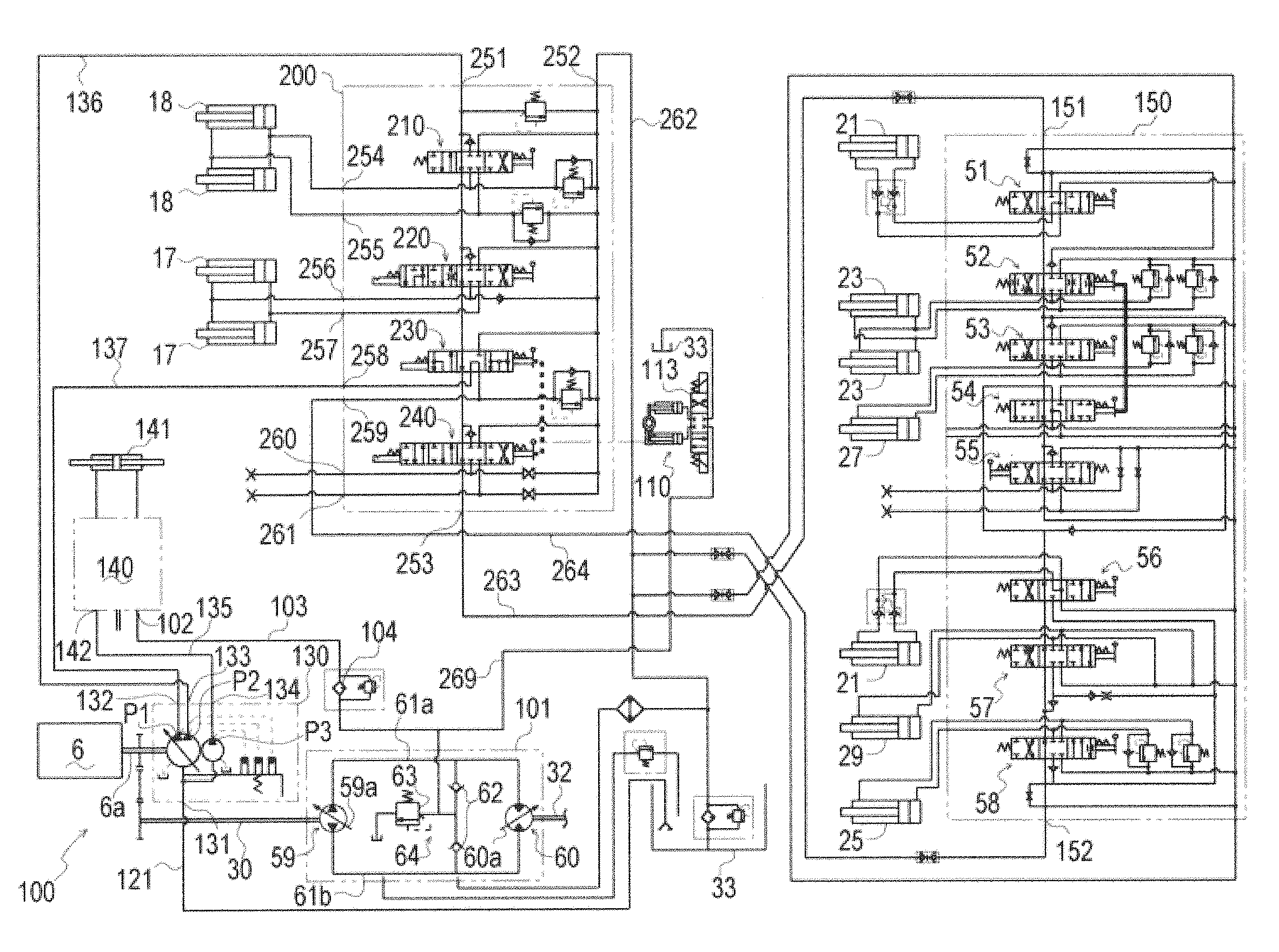
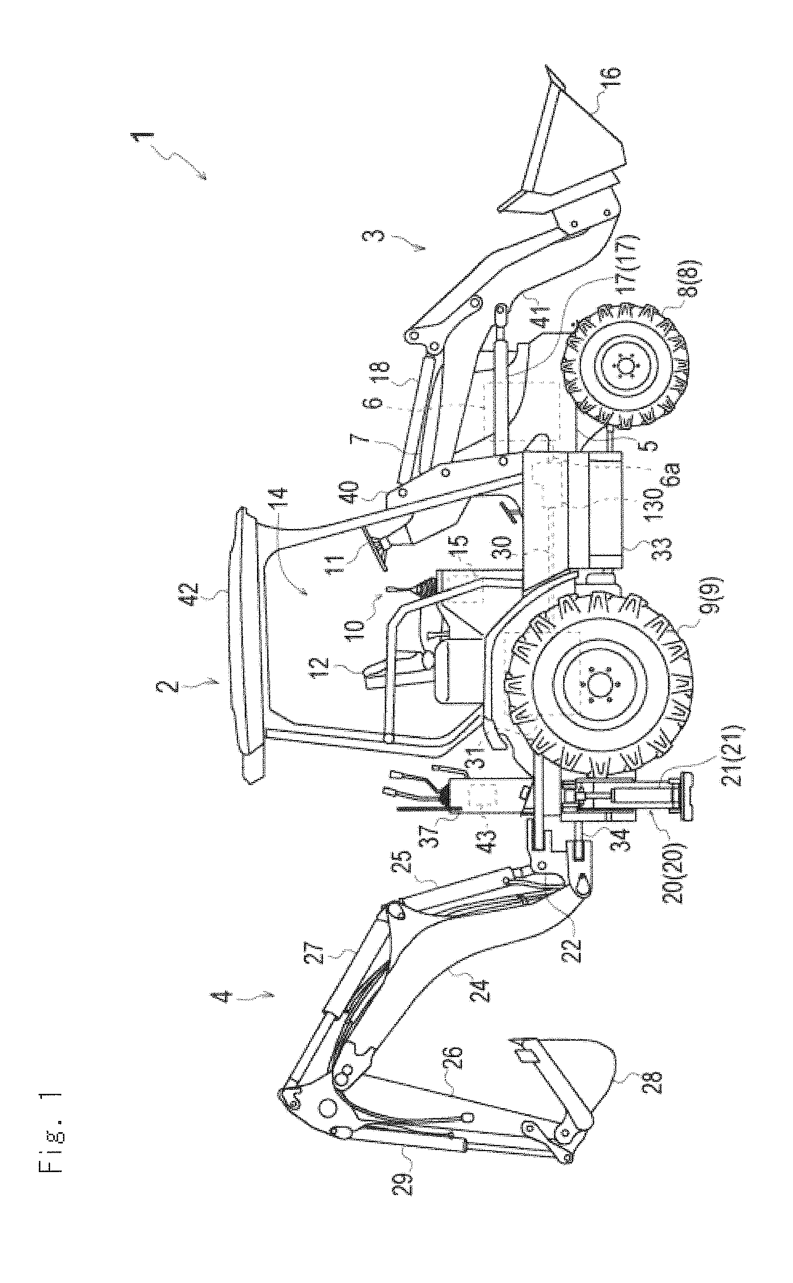
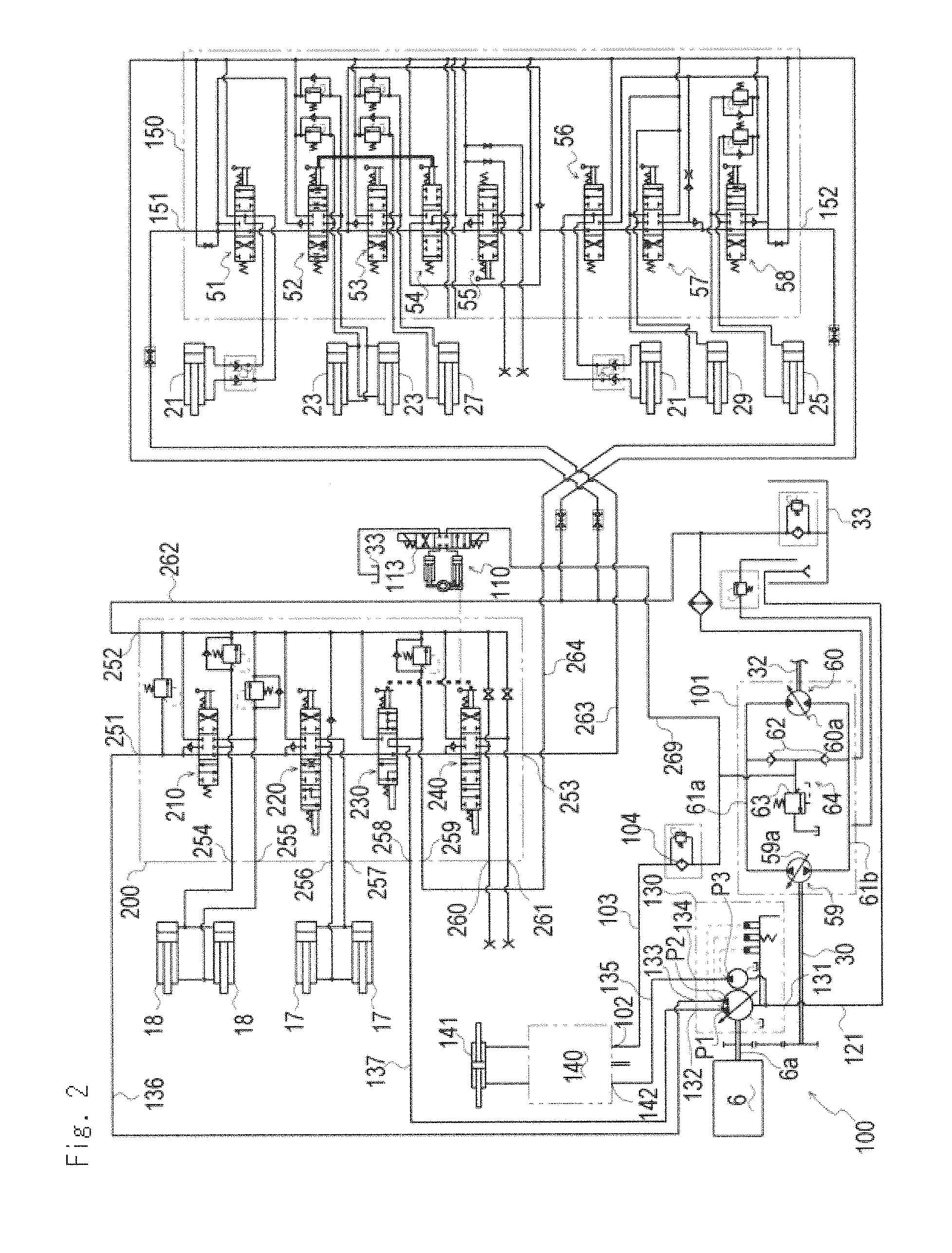
[0035]FIG. 1 is a side view of entire construction of a working vehicle according to the present invention. FIG. 2 is a hydraulic circuit diagram of the entire working vehicle. FIG. 3 is a hydraulic circuit diagram of a loader control valve section. FIG. 4 is a front view partially in section of an operation part having a selector valve operating mechanism according to the present invention. FIG. 5 is a front view partially in section of the selector valve operating mechanism. FIG. 6 is a hydraulic circuit diagram of the selector valve operating mechanism. FIG. 7 is a front view partially in section of an operation part having a selector valve operating mechanism of another embodiment.

[0036]Firstly, explanation will be given on entire construction of a working vehicle 1 according to the present invention referring to FIGS. 1, 2 and 4.

[0037]The working vehicle 1 is a backhoe loader. A loader 3 which is a ...


PUM


Abstract

The structures of oil paths and switching control of a mechanical selector valve for controlling a hydraulic actuator and the cost of parts of the mechanical selector valve are respectively simplified and reduced to levels not achievable by an electromagnetic selector valve. However, simple and quick switching operation of the mechanical selector valve by the use of a nearby switch which requires small force to actuate is difficult, and this makes the mechanical selector valve less easy to operate than the electromagnetic selector valve. A selector valve operating mechanism (110) is provided with operating pistons (176, 179) which are hydraulic pistons connected through an operation link (161) to a spool (145) of a PTO selector valve (240), an solenoid valve (113) for hydraulically controlling reciprocation of the operating pistons (176, 179), and a controller (123) which is a control device for transmitting an operation signal to the solenoid valve (113). Control of operation of the solenoid valve (113) moves the spool (145) through the operating pistons (176, 179) and the operation link (161) to switch the PTO selector valve (240).

Description

TECHNICAL FIELD[0001]The present invention relates to a selector valve operating mechanism for a working vehicle which operates a mechanical selector valve for controlling a hydraulic actuator.BACKGROUND ART[0002]Conventionally, an art is known in which a working vehicle such as a backhoe loader has a PTO hydraulic port for supplying pressure oil to a hydraulic actuator of an external hydraulic apparatus such as a breaker or a grapple, and for supply and discharge of pressure oil to the PTO hydraulic port, an electromagnetic type selector valve with an electromagnetic solenoid is employed such as an electromagnetic selector valve in which a spool in the selector valve is moved directly by an electromagnetic solenoid so as to change the route of pressure oil or an electromagnetic hydraulic selector valve in which an electromagnetic pilot valve having an electromagnetic solenoid is actuated and a main spool is moved indirectly by hydraulic pressure from the electromagnetic pilot valve...

Claims


Application Information

Patent Timeline
Patent Type & Authority Applications(United States)
IPC IPC(8): F16K31/02
CPCE02F3/964E02F9/2004E02F9/2267E02F9/2271E02F9/2275F15B2211/5059F15B2211/3111F15B2211/31576F15B2211/321F15B2211/324F15B2211/329F15B13/042
Inventor SAKAMOTO, KUNIHIKOOGATA, NAGAHIROYAMASHITA, MASAAKI
Owner YANMAR POWER TECHNOLOGY CO LTD
Learn More