Multi-chamber knee airbag

a multi-chamber, knee-high technology, applied in the direction of vehicle components, pedestrian/occupant safety arrangements, vehicular safety arrangments, etc., can solve the problems of poor gas efficiency, large generating capacity of gas generator or inflator, and inability to achieve significant generating capacity, etc., to achieve the effect of increasing pressur

Active Publication Date: 2011-07-21
HONDA MOTOR CO LTD
View PDF28 Cites 58 Cited by
  • Summary
  • Abstract
  • Description
  • Claims
  • Application Information

AI Technical Summary

Benefits of technology

[0006]According to another aspect, a leg protection device for a vehicle includes a gas generator for generating gas and a multi-chamber knee airbag operatively connected to the gas generator for receiving the gas therefrom for inflation. The airbag includes a first inflation chamber, a pair of second inflation chambers, a pair of third inflation chambers and a fourth inflation chamber. The first chamber has an inlet for directly receiving the gas generated from the gas generator. Each second inflation chamber has an inlet valve communicating with the first chamber. Each third inflation chamber has an inlet valve communicating with the first chamber. The fourth chamber has a pair of inlet valves, each inlet valve communicating with one of the pair of third chambers. The inlet valves are configured to maintain a higher pressure in the second and third chambers relative to the first and fourth chambers during inflation. Actuation of the gas generator inflates the first chamber. The gas then flows from the first chamber into each of the second chambers and the third chambers. The gas then flows from the third chambers into the fourth chamber. The separate chambers provide varying coverage for different sized occupants and different crash modes.
[0007]According to yet another aspect, a knee airbag module for a vehicle includes a gas generator for generating gas and a multi-chamber ai...

Problems solved by technology

However, if the airbag is designed to expand laterally as well, the inflation volume can become so large that a gas generator or inflator having a significantly large generating capacity is required.
Since the multi-chamber airbag has a relatively large volume, the gas gene...

Method used


Image

  • Multi-chamber knee airbag
  • Multi-chamber knee airbag
  • Multi-chamber knee airbag

Examples


Embodiment Construction

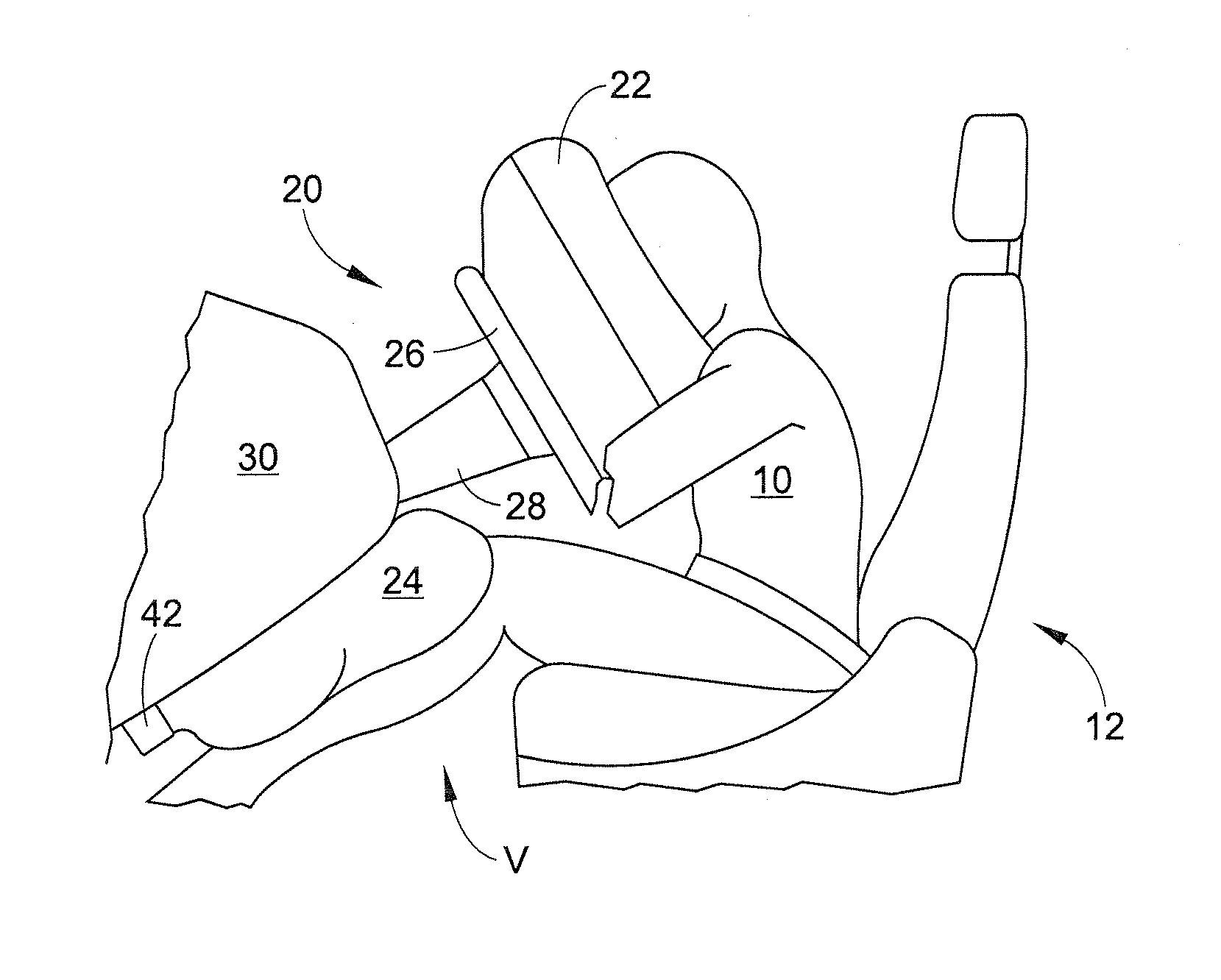
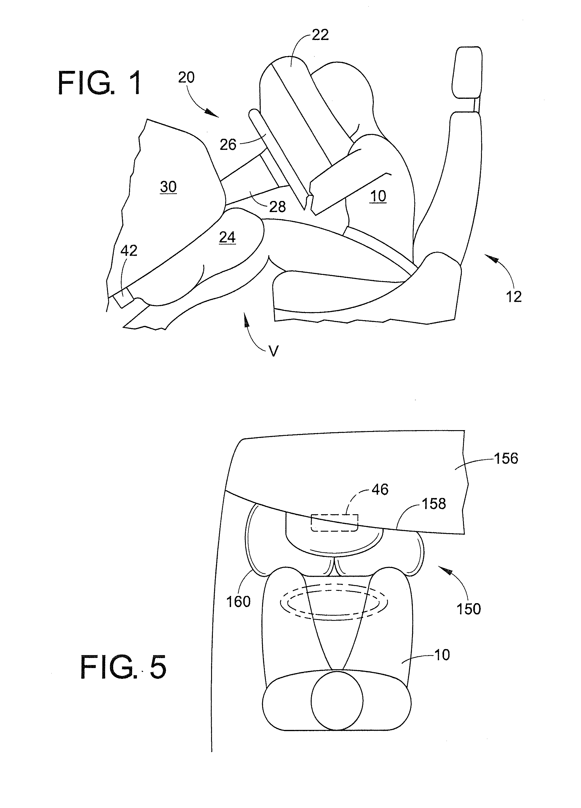
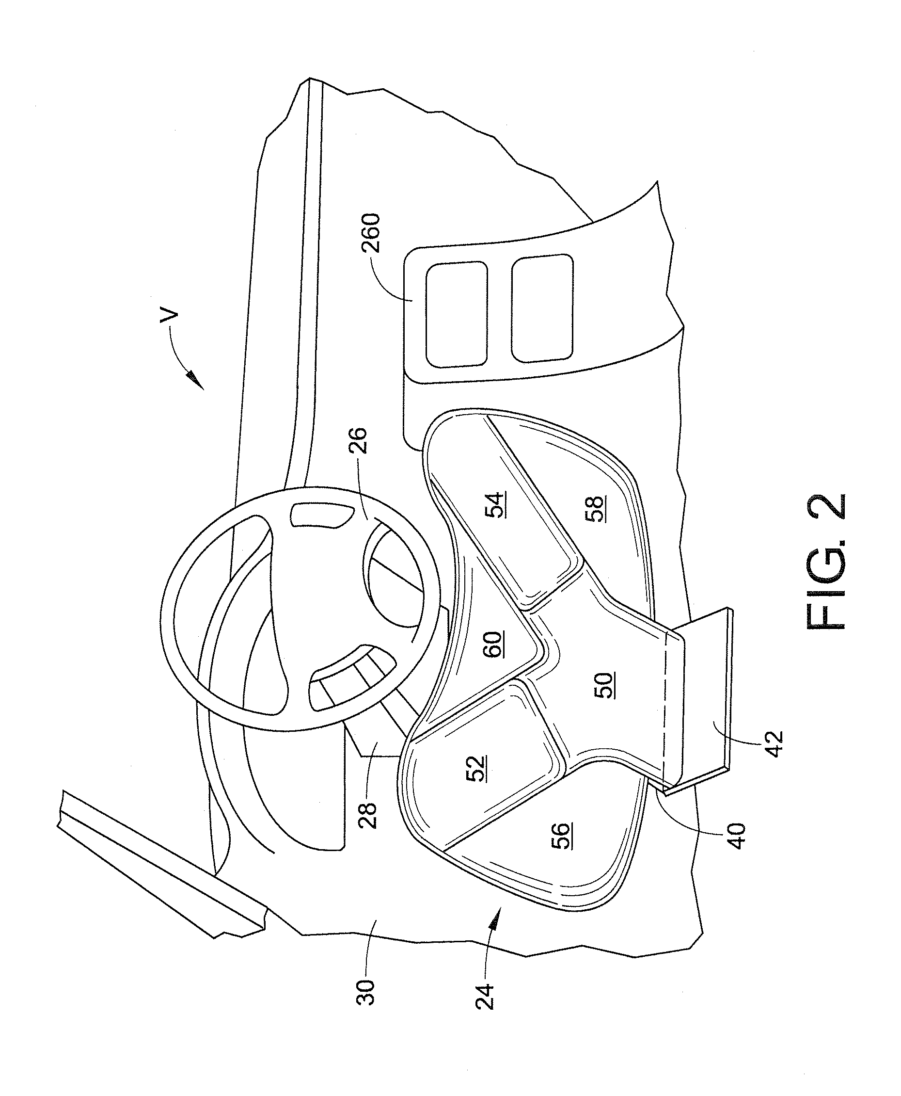
[0017]It should, of course, be understood that the description and drawings herein are merely illustrative and that various modifications and changes can be made in the structures disclosed without departing from the present disclosure. Referring now to the drawings, wherein like numerals refer to like parts throughout the several views, FIGS. 1 and 2 schematically depict an occupant or driver 10 seated in a front seat 12 of an automotive vehicle V. The vehicle V has installed therein a supplemental restraint system 20 for protecting the front-seat occupant 10 during a vehicle collision. The supplemental restraint system 20 includes a known head / torso protection device having a passenger airbag 22 and an exemplary lower protection device having a knee airbag 24. As shown, the head / torso protection device is deployed from a steering wheel 26 attached to a steering column 28. The steering column 28 projects from the dashboard 30 located in front of the driver's seat 12. The knee airba...


PUM


Abstract

An airbag module for a vehicle includes a gas generator for generating a gas and a multi-chamber airbag operatively connected to the gas generator for receiving the gas. The airbag defines a first inflation chamber, at least one second inflation chamber, at least one third inflation chamber and a fourth inflation chamber. The airbag includes internal vents configured to allow selective communication between the first chamber and each of the at least one second chamber and the at least one third chamber and selective communication between the at least one second chamber and the fourth chamber. The internal vents are configured to maintain a higher pressure in selective chambers by restricting ability of the gas to escape the selective chamber. The order of internal venting between the respective inflation chambers controls the pressure and timing of inflation of the multi-chamber airbag.

Description

BACKGROUND[0001]Exemplary embodiments herein relate to motor vehicle supplemental restraint systems, and more particularly, to a multi-chamber knee airbag for protecting an occupant from colliding with an object such as an interior panel in front of a seat in the event of a vehicle collision.[0002]Vehicles generally provide some kind of supplemental restraint system. Often, these supplemental restraint systems take the form of inflatable devices or restraints. In some cases, an inflatable restraint system includes a leg protection device having an airbag deployed in front of the vehicle occupant to receive the legs of the occupant in the event of a vehicle collision so as to protect the vehicle occupant.[0003]In one known leg protection device, a single chamber is formed inside the airbag. The occupant sitting on a vehicle seat may assume various sitting postures, for example, with knees apart and / or with legs extending sideways. The positions of the knees may be often spaced apart ...

Claims


Application Information

Patent Timeline
IPC IPC(8): B60R21/16B60R21/26
CPCB60R21/206B60R21/233B60R21/239B60R2021/2395B60R2021/23169B60R2021/23308B60R2021/23324B60R2021/0041
Inventor MILLER, RYAN A.HEITKAMP, ERIC M.
Owner HONDA MOTOR CO LTD
Why Eureka
Try Eureka