Brake device for a motor vehicle having a pressure accumulator

Inactive Publication Date: 2011-07-21
ROBERT BOSCH GMBH
View PDF7 Cites 5 Cited by
  • Summary
  • Abstract
  • Description
  • Claims
  • Application Information

AI Technical Summary

Benefits of technology

[0015]Against the background of the related art, an object of the present invention is providing a brake device for a motor vehicle, which also support

Problems solved by technology

However, when combining the deceleration effects by corresponding active power components

Method used


Image

  • Brake device for a motor vehicle having a pressure accumulator
  • Brake device for a motor vehicle having a pressure accumulator
  • Brake device for a motor vehicle having a pressure accumulator

Examples


Embodiment Construction

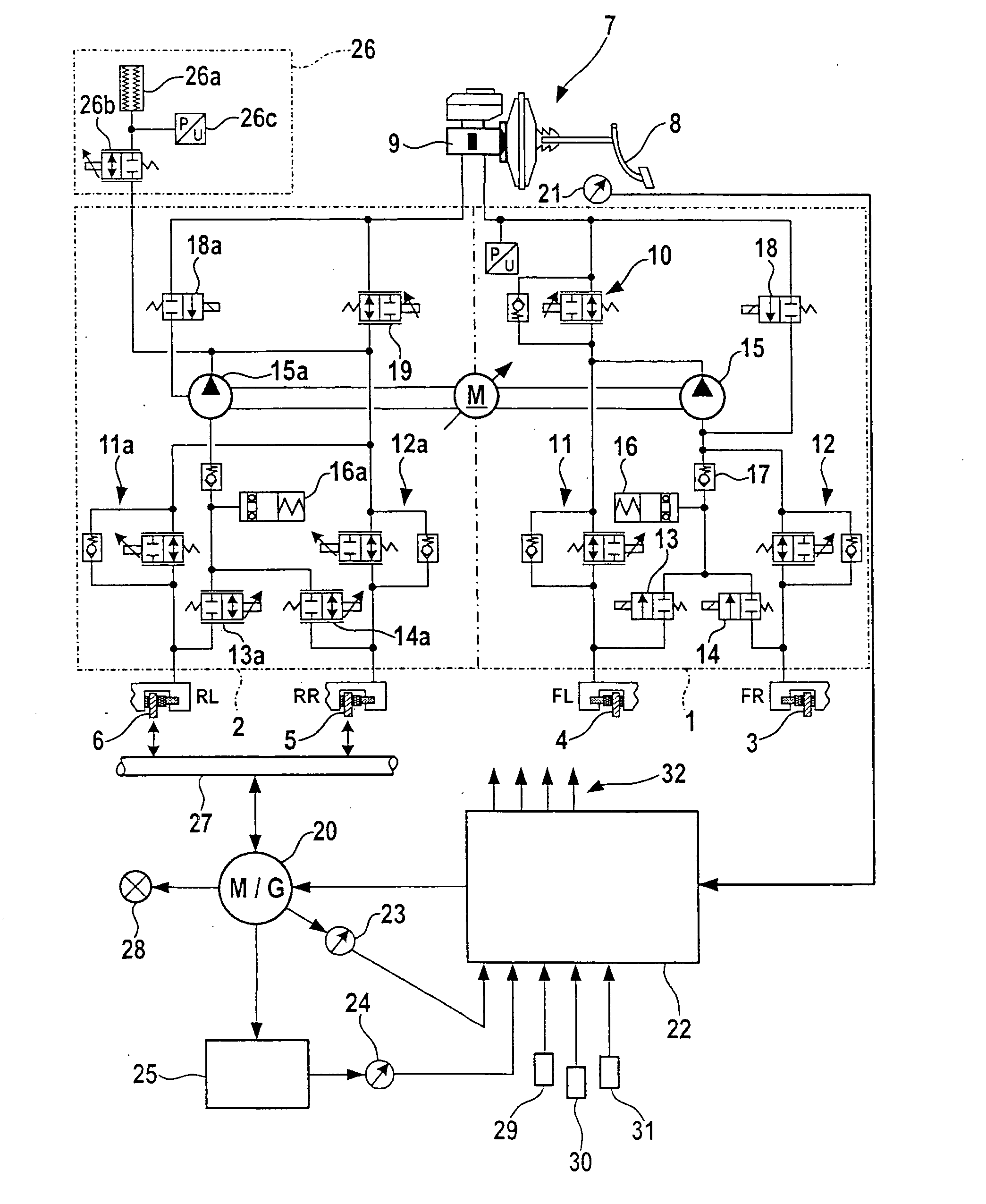
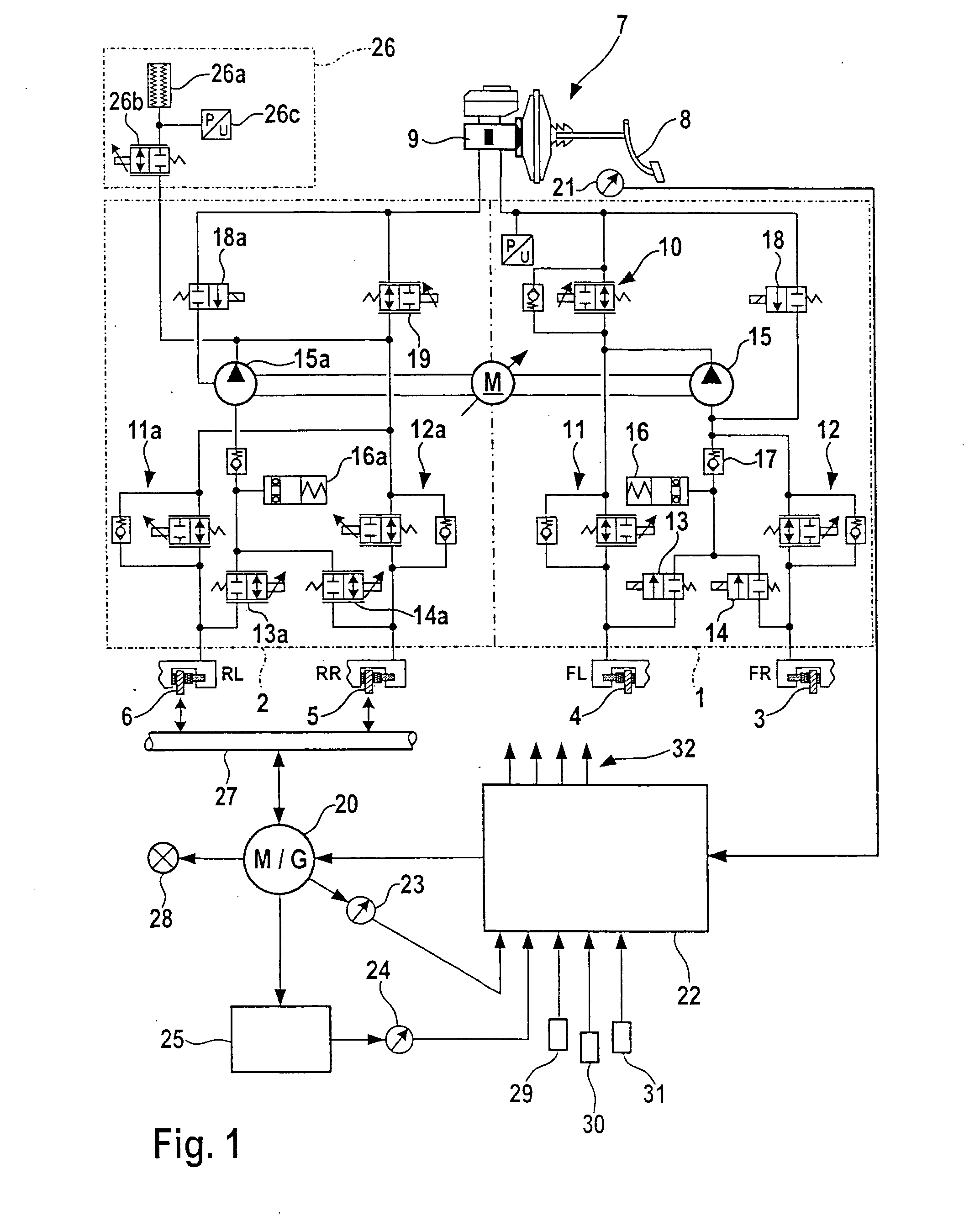
[0044]FIG. 1 shows a two-circuit brake system, which has a first brake circuit 1 on the right side of the figure, which represents the first group of brake circuits, and a second brake circuit 2, which forms the single brake circuit of the second group of brake circuits in the illustrated exemplary embodiment. However, the dash-dot lines denote merely functional boundaries and assignments; the corresponding units may be combined into common units nevertheless, e.g., into a hydraulic block.

[0045]In the following text, the function of first brake circuit 1 will be described to begin with, whereupon the special features of second brake circuit 2 will be addressed.

[0046]FIG. 1 shows a brake device having a first brake circuit 1 on the right side, which is assigned to front wheels 3, 4 of a two-axle motor vehicle, as well as a second brake circuit 2, which is assigned to rear wheels 5, 6 of the motor vehicle. The brake circuits are indicated by dash-dot lines in each case. In the specifi...


PUM


Abstract

In a brake device for a motor vehicle having a first and a second hydraulic brake circuit, the second brake circuit is decoupled from the main brake cylinder in partial braking operations, and is operated with the aid of a pressure accumulator controlled by a control device, which takes an additional deceleration effect due to an active power component, e.g., a generator, into account.

Description

BACKGROUND OF THE INVENTION[0001]1. Field of the Invention[0002]The present invention relates to multi-circuit brake systems for motor vehicles.[0003]2. Description of Related Art[0004]Such multi-circuit brake systems, particularly of the hydraulic type, have gained ground in the vehicle manufacture for reasons of efficiency and reliability through redundancy. In response to the actuation of the brake pedal, hydraulic fluid in a main brake cylinder is typically compressed and displaced to the hydraulic brake circuits.[0005]Modified constellations may result, for example, in that additional deceleration means such as connected generators in the form of the vehicle's electric generator or an electric drive motor operated as generator are integrated in the brake system in hybrid vehicles. This allows for recuperative braking, for example, which, for one, does not stress the brake and for another, recovers energy from the kinetic energy of the vehicle during braking. However, when combi...

Claims


Application Information

Patent Timeline
IPC IPC(8): B60T13/14B60T13/68B60T13/74
CPCB60T1/10B60T8/348B60T8/4072B60T8/4872B60W30/18127B60T2270/82B60W10/08B60W10/184B60T2270/604
Inventor WUERTH, GEBHARDMEHL, VOLKERKUNZ, MICHAELLEIBLEIN, MATTHIASQUIRANT, WERNER
Owner ROBERT BOSCH GMBH
Why Eureka
Try Eureka