
Vehicular batery charger, charging system, and method

a technology of electric vehicle and charging system, which is applied in secondary cell servicing/maintenance, instruments, transportation and packaging, etc., can solve the problems of exacerbated problems, unpredictable strain on the community power system, and significant limitations of electric vehicle widespread utilization, so as to reduce the rate of battery charge, and increase the charge rate of the battery

Active Publication Date: 2011-07-21
AUSTIN CHRISTOPHER B
View PDF15 Cites 323 Cited by
  • Summary
  • Abstract
  • Description
  • Claims
  • Application Information

AI Technical Summary

Benefits of technology

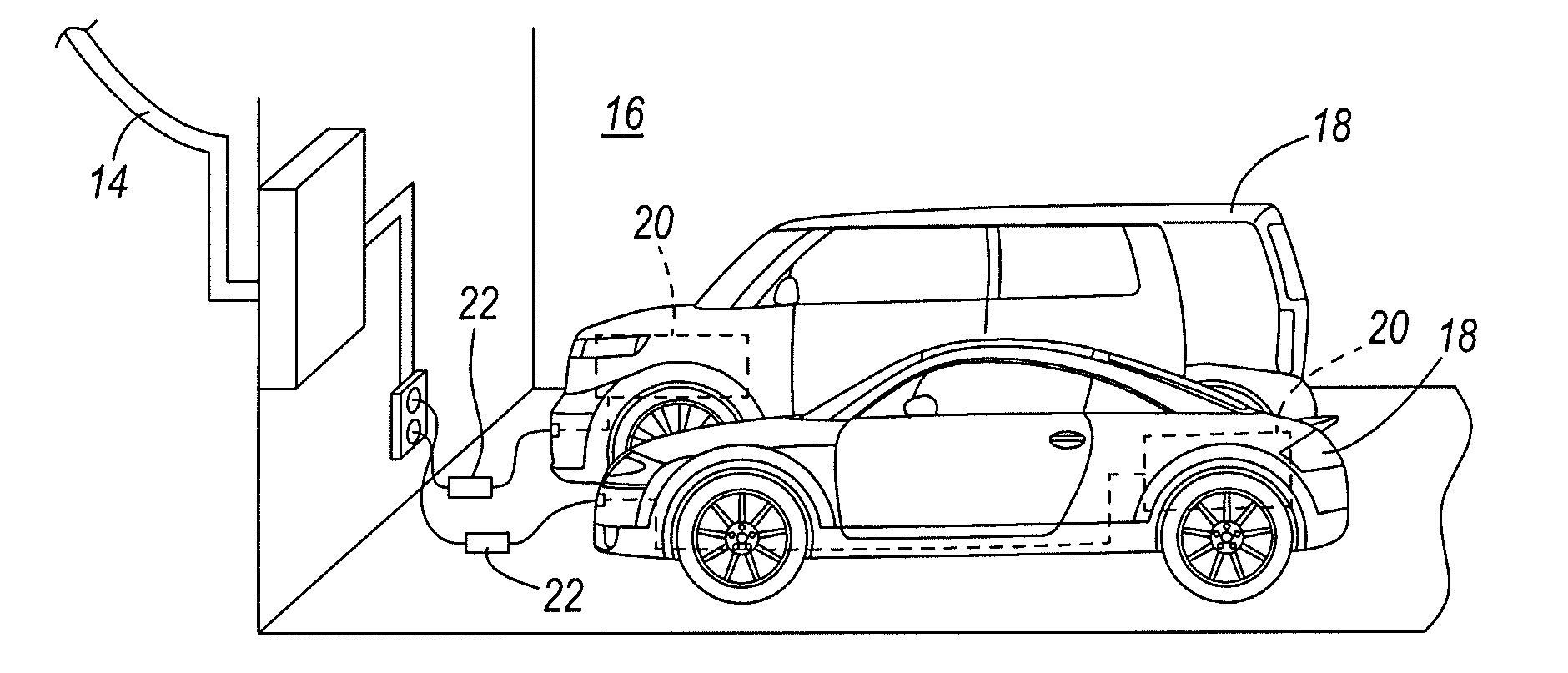
[0006]Some embodiments of the present invention provide a vehicle charger for charging a battery of a vehicle in the course of a charging session, wherein the vehicle charger comprises a controller; a display coupled to the controller and adapted to display a time; and a user-manipulatable control coupled to the controller and operable by a user to enter a time of day at which the charging session will end, the controller changing the supply of electric power to the vehicle battery during the course of the charging session by at least one of increasing a rate of charge of the battery, decreasing the rate of charge of the battery, starting battery charging, or stopping battery charging based at least in part upon the time needed to charge the vehicle battery by the time of day entered by the user.
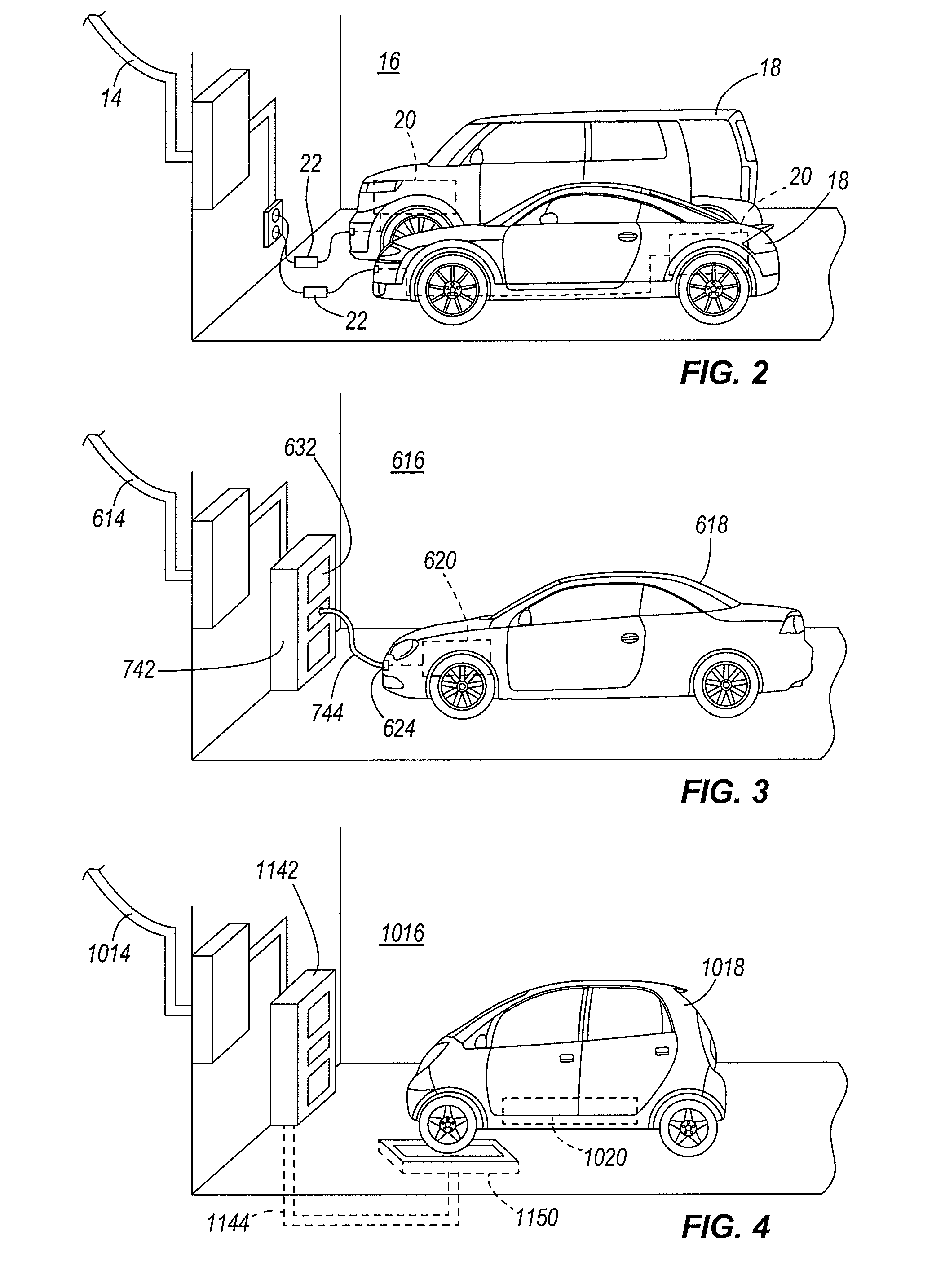
[0007]In some embodiments, a vehicle charger for charging a battery of a vehicle is provided, wherein the vehicle charger comprises a display mounted within the vehicle within reach of a user seated within the vehicle; a user-manipulatable control within reach of the user seated within the vehicle and by which a user can enter a time of day; a controller coupled to the display and to the battery, the controller changing a supply of electric power to charge the battery during the course of a charging session by at least one of increasing a rate of charge of the battery, decreasing the rate of charge of the battery, starting battery charging, or stopping battery charging based at least in part upon the time of day entered by the user.
[0015]In some embodiments, a vehicle charger for charging a battery of a vehicle and adapted for communication with a first controller remote from the vehicle and vehicle charger is provided, and comprises a display; a user-manipulatable control; a second controller coupled to the display and operable to change a supply of electric power to charge the battery during the course of a charging session by at least one of increasing a rate of charge of the battery, decreasing the rate of charge of the battery, starting battery charging, or stopping battery charging; and at least one of a transmitter and a receiver coupled to the second controller and adapted for communication with the first controller, the second controller responsive to at least one signal from the first controller by changing a charging state of the vehicle charger based at least in part upon the time of day entered by the user.
[0017]In some embodiments, a vehicle charger for charging a battery of a vehicle is provided, and comprises a controller; a vehicle charger battery coupled to the controller; and an electrical power cord releasably attachable to at least one of the vehicle and the vehicle charger battery to supply power from the vehicle charger battery to the battery of the vehicle, wherein the controller is operable to change a supply of electric power to the vehicle charger battery during the course of a charging session by at least one of increasing a rate of charge of the vehicle charger battery, decreasing the rate of charge of the vehicle charger battery, starting charging of the vehicle charger battery, or stopping charging of the vehicle charger battery based at least in part upon a time of day.

Problems solved by technology

Unfortunately, significant limitations exist to the widespread utilization of electric vehicles.
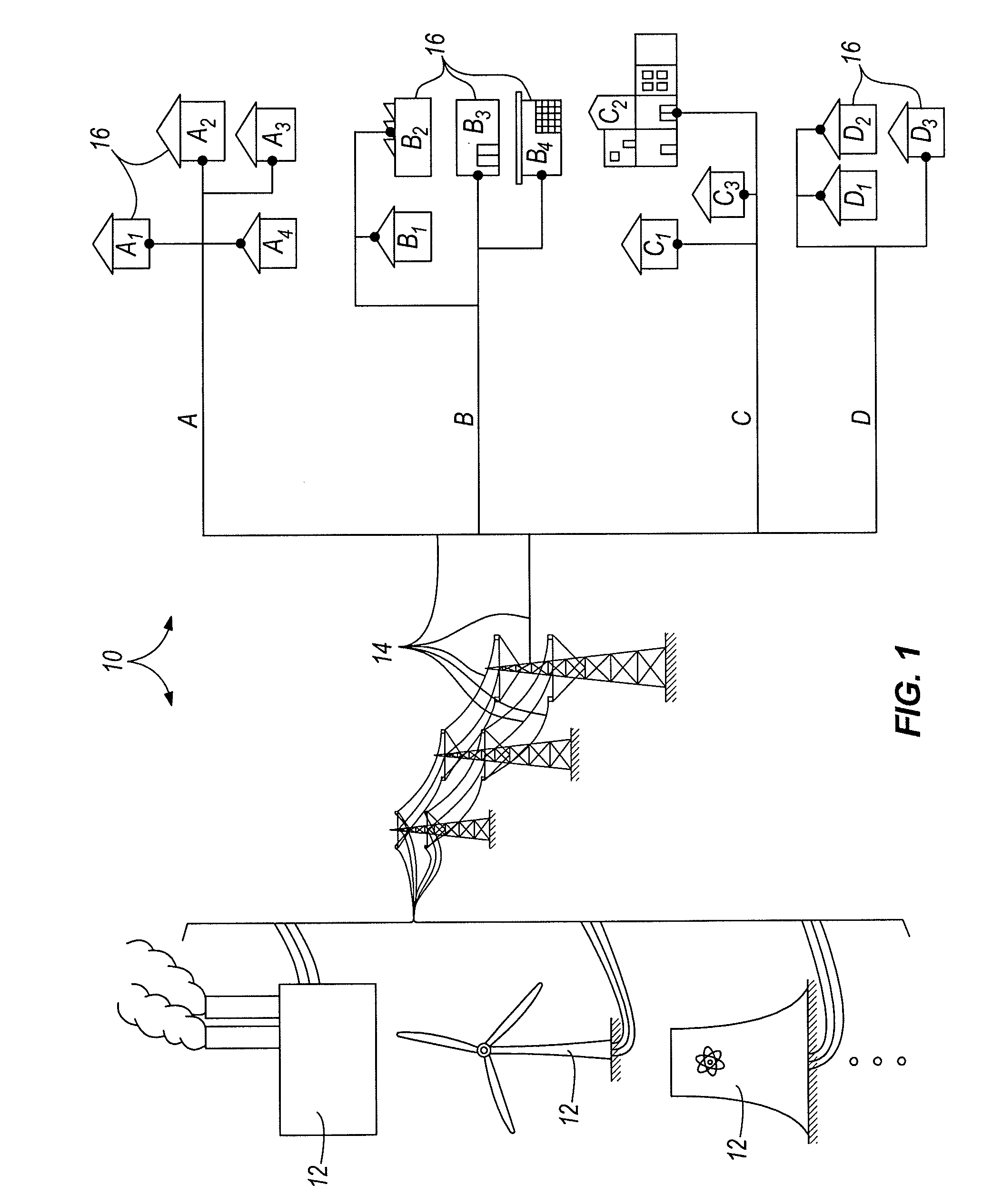
The introduction of an electrical vehicle as another daily draw of electric power for a household would place unprecedented strain on community power systems, many of which are already incapable of meeting peak demands.
This problem is exacerbated by the fact that in some cases, the daily draw of electric power to charge the battery of an electric vehicle may be the highest of a household.
Simply put, existing power infrastructure for most communities is incapable of meeting the demand that widespread use of rechargeable electric vehicles would place on the infrastructure.

Method used


Image

  • Vehicular batery charger, charging system, and method
  • Vehicular batery charger, charging system, and method
  • Vehicular batery charger, charging system, and method

Examples


Embodiment Construction

[0050]Before any embodiments of the present invention are explained in detail, it is to be understood that the present invention is not limited in its application to the details of construction and the arrangement of components set forth in the following description or illustrated in the accompanying drawings. The invention is capable of other embodiments and of being practiced or of being carried out in various ways. Also, it is to be understood that the phraseology and terminology used herein is for the purpose of description, and should not be regarded as limiting. The use of “including,”“comprising,” or “having” and variations thereof herein is meant to encompass the items listed thereafter and equivalents thereof as well as additional items. Unless specified or limited otherwise, the terms “mounted,”“connected,”“supported,” and “coupled” and variations thereof are used broadly and encompass both direct and indirect mountings, connections, supports, and couplings. Further, “conn...


PUM


Abstract

A vehicle battery charger and a vehicle battery charging system are described and illustrated, and can include a controller enabling a user to enter a time of day at which the vehicle battery charger or system begins and / or ends charging of the vehicle battery. The vehicle battery charger can be separate from the vehicle, can be at least partially integrated into the vehicle, can include a transmitter and / or a receiver capable of communication with a controller that is remote from the vehicle and vehicle charger, and can be controlled by a user or another party (e.g., a power utility) to control battery charging based upon a time of day, cost of power, or other factors.

Description

CROSS-REFERENCE TO RELATED APPLICATIONS[0001]Priority is hereby claimed to U.S. Provisional Patent Application No. 61 / 189,353 filed on Aug. 18, 2008, the entire contents of which are incorporated herein by reference.BACKGROUND[0002]n light of the ever-rising costs of energy in the global market, energy consumers of all types seek to reduce the impact such costs to the greatest extent possible. One popular manner of doing so is the use of vehicles that do not rely solely (and in some cases, at all) upon petroleum products as a source of energy. Many such vehicles have been developed that rely exclusively or in large part on batteries that must be recharged from a source of electrical power external to the vehicle. Such vehicles are referred to hereinafter simply as “electric vehicles,” it being understood that this term refers to any vehicle requiring an external supply of electrical power to charge the vehicle for normal use. By way of example and without limitation, the term “elect...

Claims


Application Information

Patent Timeline
IPC IPC(8): H02J7/00
CPCB60L11/1824B60L2230/12B60L2230/16G01R31/3689H01M10/44H02J7/0042H02J7/0047Y02T10/7005Y02T10/7088Y02T90/128Y02T90/14Y02T90/16Y02T90/163Y04S10/126Y02E60/721Y02T90/121B60L11/1844B60L53/14B60L53/38B60L53/63B60L53/18B60L53/305B60L53/68G01R31/371B60L53/126Y02E60/00Y02E60/10H02J7/0048Y02T10/7072Y02T10/70Y02T90/12Y02T90/167B60L2250/16
Inventor AUSTIN, CHRISTOPHER B.
Owner AUSTIN CHRISTOPHER B
Learn More