Vehicle control device
A vehicle control device, vehicle technology, applied in the direction of control device, battery/fuel cell control device, control drive, etc.
- Summary
- Abstract
- Description
- Claims
- Application Information
AI Technical Summary
Problems solved by technology
Method used
Image
Examples
no. 1 approach
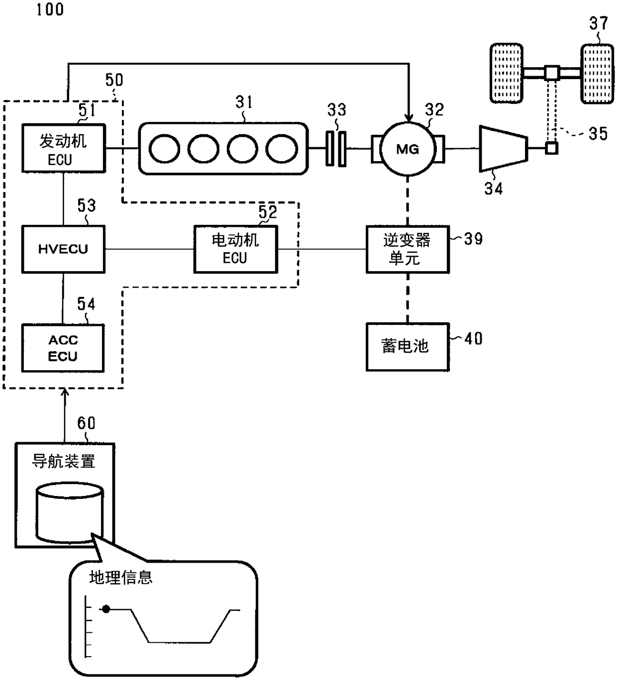
[0041] Embodiments of the present invention will be described with reference to the drawings. In the following description, the vehicle control device of the present embodiment is applied to a hybrid vehicle that obtains driving force for vehicle running from an engine and a running electric motor. Hereinafter, a hybrid vehicle is simply referred to as a vehicle. In addition, in each of the following embodiments, the same reference numerals are assigned to the same or equivalent parts in the drawings, and the descriptions are referred to for the same reference numerals.
[0042] figure 1 It is a figure which shows the structure of the vehicle 100 as an example. Vehicle 100 mainly includes an engine 31 , an electric motor 32 composed of a motor generator, a clutch 33 , a transmission 34 , a drive shaft 35 , drive wheels 37 , an inverter unit 39 , a battery (battery) 40 , and a vehicle control device 50 . Furthermore, the vehicle 100 includes a navigation device 60 from which...
no. 2 approach
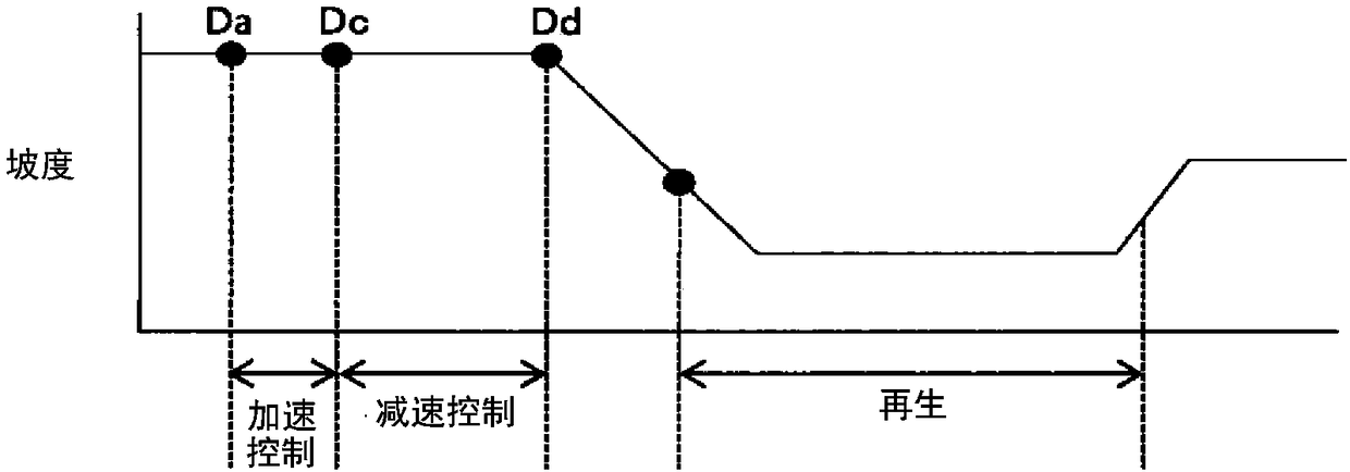
[0090] In this second embodiment, the structure for performing regeneration during a downhill descent is the same as that of the first embodiment, but differs from the first embodiment in that the vehicle 100 is accelerated during a part of the downhill section where regeneration is performed. Downhill acceleration control.
[0091] FIG. 10 is a diagram for explaining processing accompanying reproduction in the second embodiment. Figure 10A is a diagram showing the traveling route of the vehicle 100 and the gradient of the traveling route. Figure 10B This is a diagram for explaining changes in the target vehicle speed. Figure 10C It is a graph for explaining changes in the charge rate SOC of the storage battery 40 . Figure 10D It is a figure explaining the change of the drive force of the vehicle 100.
[0092] like Figure 10A-10D As shown, in the second embodiment, the vehicle 100 performs regeneration during the downhill process meeting the prescribed conditions. In...
no. 3 approach
[0129] Setting the deceleration start position Dc based on the target vehicle speed V1 is just one example. For example, it may be set based on the reduction target value of the charging rate SOC. Figure 16 It is a flowchart showing setting of the deceleration start position Dc in the third embodiment. Figure 16 The flowchart shown is for example image 3 The processing adopted in step S14 of . also, Figure 17 It is a graph showing the relationship between the reduction target value of the charging rate SOC (SOC reduction target value) and the distance (distance between two points) L from the downhill gradient start position Dd to the deceleration start position Dc.
[0130] exist Figure 16 In step S144, the ACCECU 54 sets the SOC lowering target value. SOC reduction target value with Figure 9 The same as shown, are set within the range of thresholds Sa to Sb.
[0131] In step S145, the ACCECU 54 sets the driving force upper limit value MD. Driving force upper lim...
PUM
 Abstract
Description
Claims
Application Information
 - R&D
- Intellectual Property
- Life Sciences
- Materials
- Tech Scout
- Unparalleled Data Quality
- Higher Quality Content
- 60% Fewer Hallucinations
Browse by: Latest US Patents, China's latest patents, Technical Efficacy Thesaurus, Application Domain, Technology Topic, Popular Technical Reports.
© 2025 PatSnap. All rights reserved.Legal|Privacy policy|Modern Slavery Act Transparency Statement|Sitemap|About US| Contact US: help@patsnap.com


