Electrical power supply apparatus controlling method and discharging method for using the same

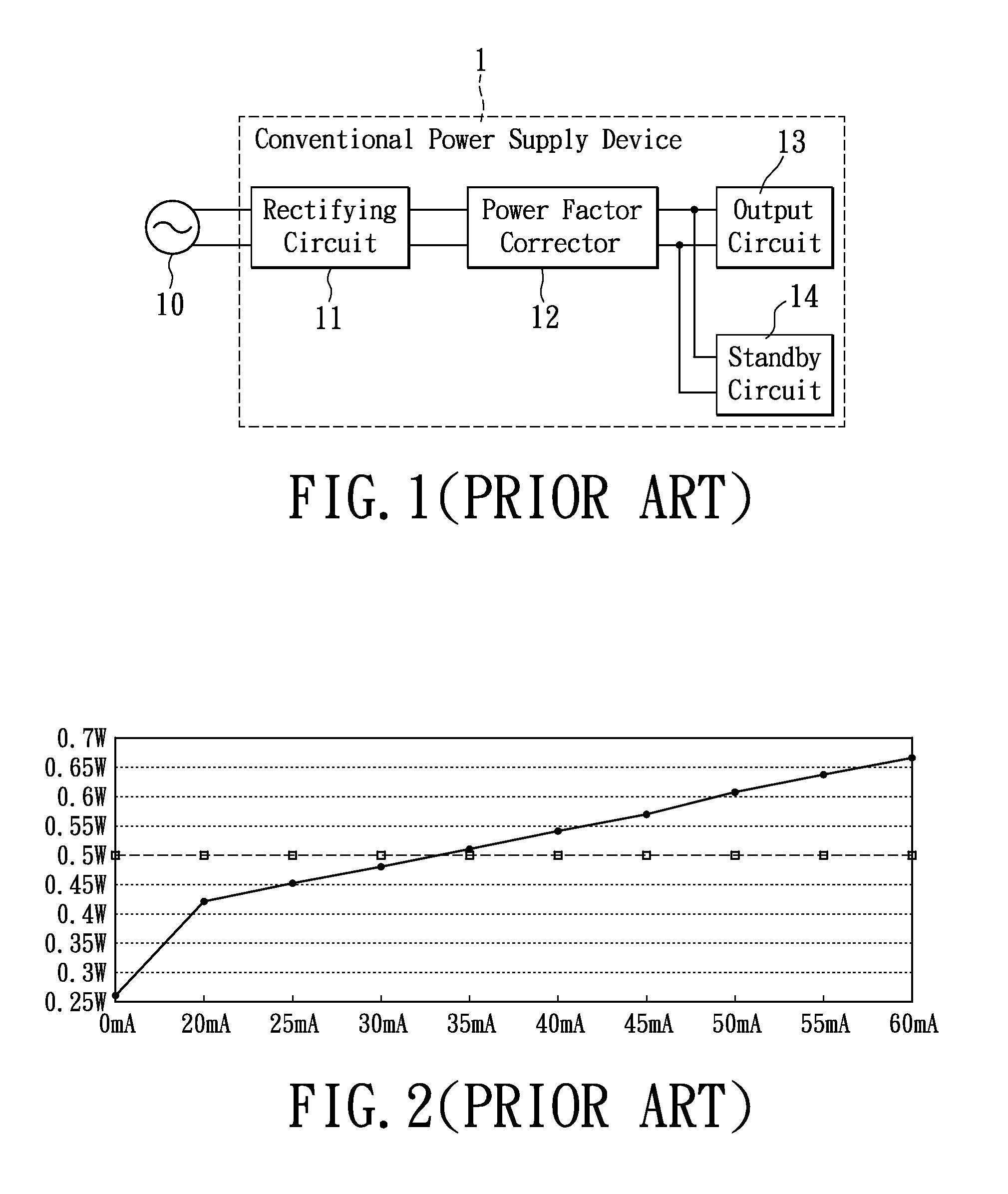
a technology of electrical power supply and control method, which is applied in the direction of emergency power supply arrangement, process and machine control, instruments, etc., can solve the problems of inability to meet the strict specifications of power consumption and the power consumption of the conventional power supply device b>1/b>, so as to enhance the stability of the electrical power supply apparatus and promote industrial upgrading

Inactive Publication Date: 2011-07-21
LITE ON ELECTRONICS (GUANGZHOU) LTD +1
View PDF2 Cites 10 Cited by
  • Summary
  • Abstract
  • Description
  • Claims
  • Application Information

AI Technical Summary

Benefits of technology

[0014]The technique proposals according to the present invention are obviously different than the conventional technique, in which the controlling method and the discharging method in accordance with the electrical power supply apparatus in a standby operating mode are provided for achieving minimum power consumption and precisely controlling the discharging time of the bulk capacitor, such that the discharging time is not affected even if the standby power consumption is reduced, thereby enhancing stability of the electrical power supply apparatus. And the aforementioned controlling method, discharging method of the electrical power supply is obviously in conformity with the strict standards of the EuP Directive, to promote industrial upgrading.

Problems solved by technology

However, conventional power supply devices are unable to reach the harsh conditions.
Yet by applying the above mentioned method, power consumption of the conventional power supply device 1 is unable to meet the strict specifications for power consumption.

Method used


Image

  • Electrical power supply apparatus controlling method and discharging method for using the same
  • Electrical power supply apparatus controlling method and discharging method for using the same
  • Electrical power supply apparatus controlling method and discharging method for using the same

Examples


Embodiment Construction

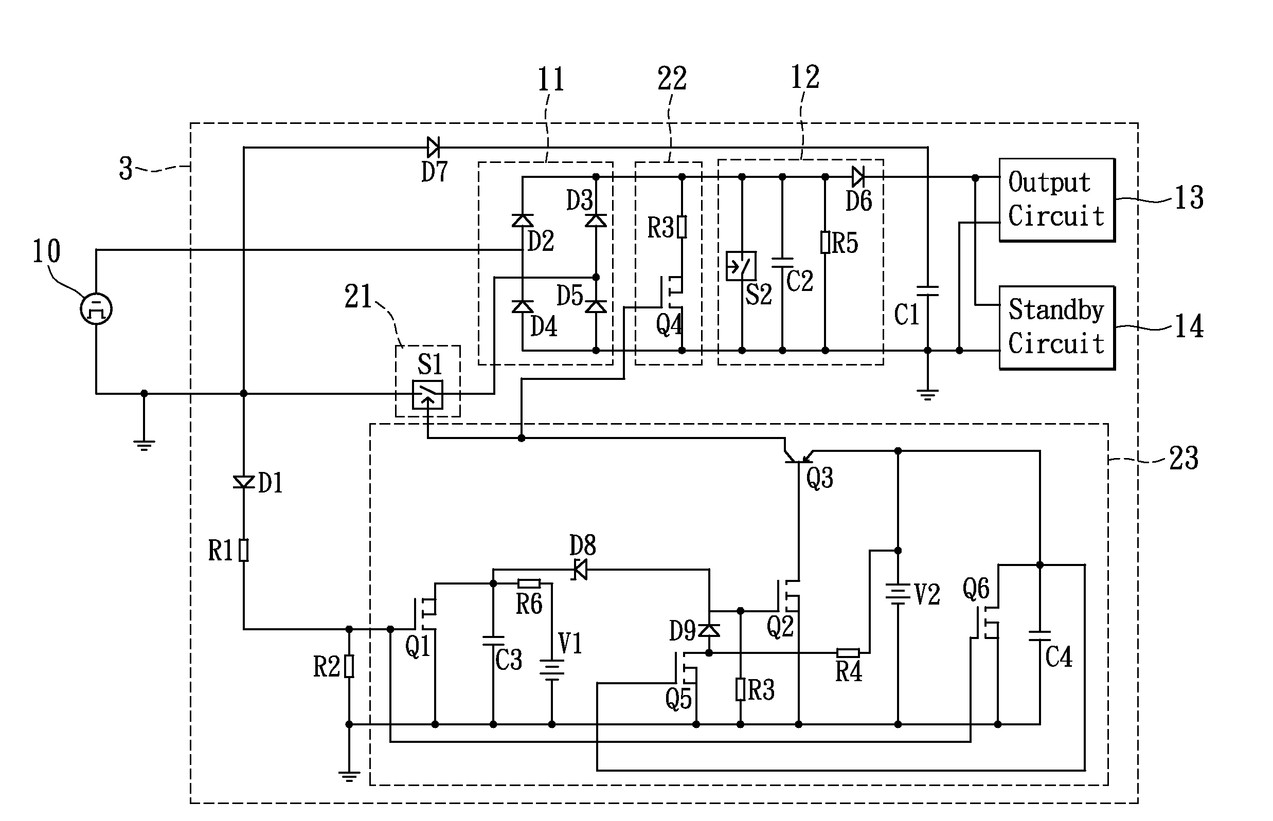
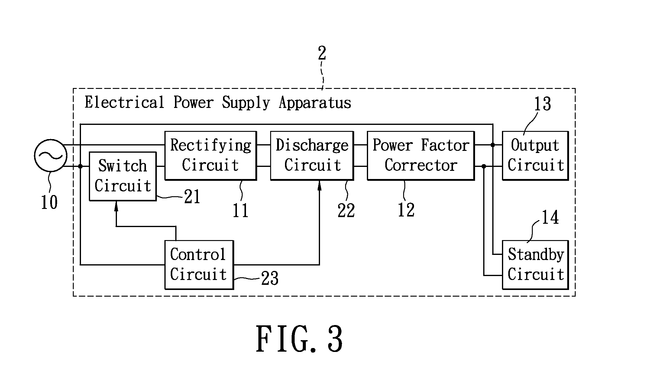
[0021]Please refer to FIG. 3, in which a system schematic diagram of an embodiment of the electrical power supply apparatus in accordance with certain aspects of the present invention is demonstrated.

[0022]An electrical power supply apparatus 2, includes a rectifying circuit 11, connected to an external power source 10 by way of a switch circuit 21, for receiving an external power signal of the external power source 10 and rectifying the external signal to generate a rectification signal. The switch circuit 21 is controlled by a control signal generated from a control circuit 23. In a normal operating mode, the switch circuit 21 conducts, such that the external power signal is transferred to an output circuit 13 by ways of the rectifying circuit 11, a discharge circuit 22, a power factor corrector 12. Herein, the switch circuit 21 and the discharge circuit 22 are controlled to be conducted with respect to the output circuit 13 or by means of the control circuit 23; in a standby oper...


PUM


Abstract

Disclosed is an electrical power supply apparatus, comprising a switch circuit; an output circuit connected to an external power source for outputting electrical power primarily; a standby circuit connected to the external power source for outputting standby power; a discharge circuit connected between the output circuit and the external power source, to form a discharge path; and a control circuit, connected to the external power source, being capable of conducting the switch circuit for transferring a power signal of the external power source to the output circuit in a normal mode, being capable of cutting off the switch circuit for transferring a first or a second period of the power signal to the standby circuit in a standby mode, and being capable of conducting the discharge circuit for allowing the electrical power supply apparatus to discharge via the discharge circuit as the external power source is being removed.

Description

BACKGROUND OF THE INVENTION[0001]1. Field of the Invention[0002]The present invention relates to an electrical power supply apparatus, and more particularly, to a controlling method and a discharging method of an electrical power supplier in a standby operating mode.[0003]2. Description of Related Art[0004]With the advancement of technology in modern life, a variety of electronic devices providing various different functions are facilitated to accelerate the multimedia communication among people, e.g., a television, a computer, a workstation, a domain, etc., and also require a larger and more stable power supply quality correspondingly. A lot of daily activities are depending on computer equipments, e.g., work, game, communication, and data processing. Therefore, the computer equipments must be able to function steadily so as to facilitate people to use them. At present, conventional computer equipments generally include central processing units, i.e. CPU, chipsets, memory units, st...

Claims


Application Information

Patent Timeline
Patent Type & Authority Applications(United States)
IPC IPC(8): G05F3/08
CPCG06F1/32H02J9/005Y02B70/16H02M2001/0032H02M7/06H02M1/0032Y02B70/10Y02B70/30Y04S20/20
Inventor YU, WEI-CHENGHSU, YUN-CHIEH
Owner LITE ON ELECTRONICS (GUANGZHOU) LTD
Why Eureka
Try Eureka