Sensor apparatus and electronic apparatus

a technology of electronic equipment and sensor, applied in the direction of electric digital data processing, instruments, computing, etc., can solve the problems of large number of components, large number of movements of touch surfaces, and complex structure, and achieve the effect of improving the s/n ratio of detected signals and large values

Inactive Publication Date: 2011-07-21
SONY CORP
View PDF12 Cites 207 Cited by
  • Summary
  • Abstract
  • Description
  • Claims
  • Application Information

AI Technical Summary

Benefits of technology

[0008]In view of the circumstances as described above, there is a need for a sensor apparatus that has a simple structure and less number of components and an electronic apparatus including the sensor apparatus.
[0053]As described above, according to the embodiments of the present invention, a sensor apparatus that has a simple structure and less number of components and an electronic apparatus including the sensor apparatus can be provided.

Problems solved by technology

In the touchpad disclosed in Patent Document 1, however, a movement amount of the touch surface is restricted by the elastic force of the springs.
Therefore, since the springs each having an adequate elastic force need to be incorporated at appropriate positions, the number of components becomes large and the structure becomes complex, which is a large problem in miniaturizing the touchpad.

Method used


Image

  • Sensor apparatus and electronic apparatus
  • Sensor apparatus and electronic apparatus
  • Sensor apparatus and electronic apparatus

Examples


first embodiment

(Structure of Sensor Apparatus)

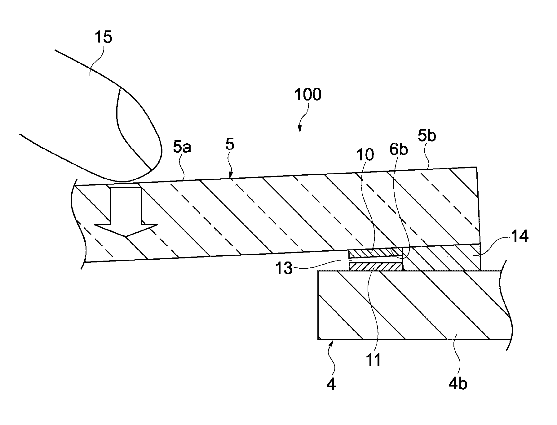
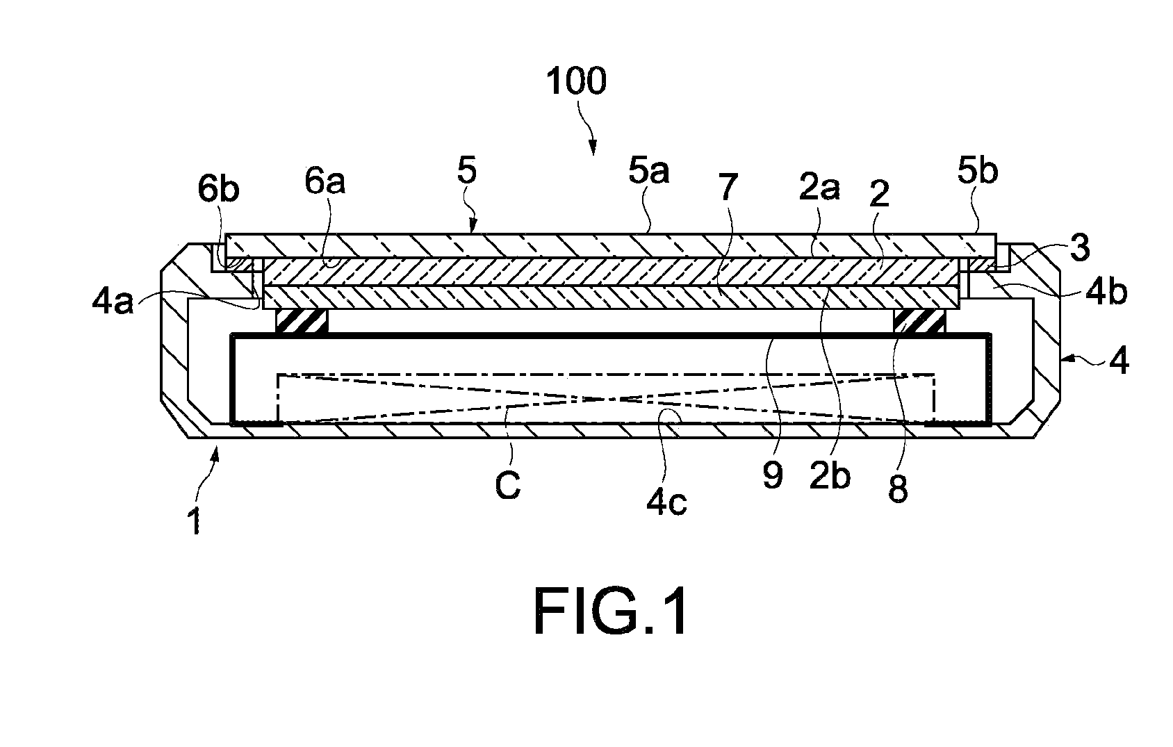
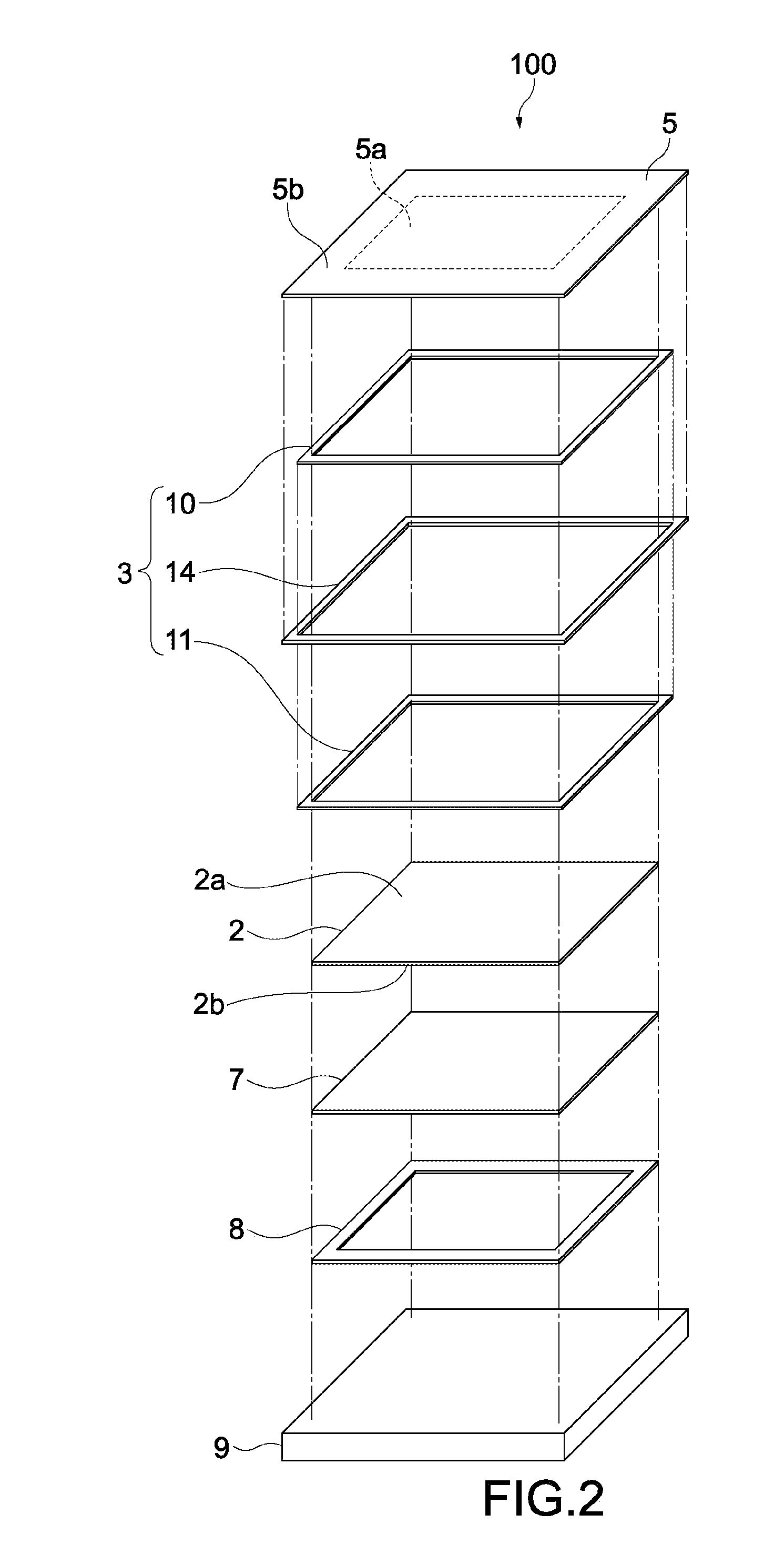
[0085]FIG. 1 is a cross-sectional diagram schematically showing a sensor apparatus according to a first embodiment of the present invention. FIG. 2 is an exploded perspective view schematically showing the sensor apparatus shown in FIG. 1. In FIG. 2, an illustration of a frame of the sensor apparatus to be described later is omitted.

[0086]A sensor apparatus 100 includes a casing 1, a touch panel 2 provided inside the casing 1, and a pressure-sensitive sensor 3. The casing 1 includes a frame 4 on which an opening 4a is formed and a display cover 5 that is fixed to the frame 4 so as to cover the opening 4a. The opening 4a covered by the display cover 5 constitutes a part of an inner space of the casing 1. The touch panel 2 is supported by the display cover 5 so as to be positioned at the opening 4a.

[0087]As shown in FIG. 2, the display cover 5 is rectangular and includes an operation area 5a that is pressed by an operator (not shown) such as a finger an...

second embodiment

[0119]Next, a sensor apparatus according to a second embodiment of the present invention will be described. In the following description, parts having the same structure and operation as those of the sensor apparatus 100 described in the above embodiment will be denoted by the same symbols, and descriptions thereof will be omitted or simplified.

[0120]FIG. 8 is a cross-sectional diagram schematically showing an enlarged pressure-sensitive sensor of the sensor apparatus according to the second embodiment of the present invention. In a sensor apparatus 200 of this embodiment, a structure of the pressure-sensitive sensor is different from that of the sensor apparatus 100 of the first embodiment. Therefore, that point will mainly be described.

[0121]A pressure-sensitive sensor 203 includes the first electrode 10 and the second electrode 11 opposing each other and a differential electrode (third electrode) 216. The differential electrode 216 is provided between the first electrode 10 and t...

third embodiment

[0132]FIG. 11 is a cross-sectional diagram schematically showing an enlarged pressure-sensitive sensor of a sensor apparatus according to a third embodiment of the present invention. A sensor apparatus 300 of this embodiment is obtained by providing a shield layer 317 (conductive layer) in the pressure-sensitive sensor 203 of the second embodiment.

[0133]As shown in FIG. 11, the shield layer 317 is provided between the differential electrode 216 and the circumferential area 5b while being opposed to the differential electrode 216. The shield layer 317 is bonded to the inner surface 6b of the circumferential area 5b by the adhesive 12a. An adhesive 12c is provided between the differential electrode 216 and the shield layer 317, and the shield layer 317 and the differential electrode 216 are opposed to each other with the adhesive 12c interposed therebetween as shown in FIG. 11.

[0134]For the shield layer 317, the same conductive material as the first electrode 10, the second electrode ...


PUM


Abstract

A sensor apparatus includes: a display cover including an operation area that is pressed by an operator and a circumferential area located on the circumference of the operation area; a frame including an opening covered by the operation area and a fixing portion that fixes the circumferential area; a touch panel that is supported by the display cover to be positioned at the opening and detects a position at which the operator comes into contact with the operation area; and a pressure-sensitive sensor that is provided between the display cover and the frame, includes a first electrode and a second electrode opposed to the first electrode, and detects a pressing force with respect to the operation area based on a change of a capacitance between the first electrode and the second electrode that corresponds to a deflection amount of the display cover.

Description

BACKGROUND OF THE INVENTION[0001]1. Field of the Invention[0002]The present invention relates to a sensor apparatus equipped with a touch panel, and an electronic apparatus.[0003]2. Description of the Related Art[0004]From the past, as an electronic apparatus such as a personal computer, there is known an electronic apparatus that is equipped with a touchpad. Regarding such an electronic apparatus, an input operation is made by pressing a touch surface of the touchpad using a finger or a touch pen and detecting a position pressed by the finger or the like. For example, Japanese Patent Application Laid-open No. Hei 10-198503 (FIG. 2 etc.) (hereinafter, referred to as Patent Document 1) discloses a touchpad that uses a variable capacitor to measure a position and amount of a force applied to a touch surface.[0005]In the touchpad disclosed in Patent Document 1, one of two plates (electrodes) of the variable capacitor is provided on a flat top member that supports the touch surface. The...

Claims


Application Information

Patent Timeline
Patent Type & Authority Applications(United States)
IPC IPC(8): G06F3/045
CPCG06F3/044G06F3/0414G06F3/0447G06F3/0445
Inventor HONDA, HIDETOSHIKANEHIRA, HIROKIKAWAGUCHI, HIROTOMIYATA, KAZUTOMOISHIGAKI, MASATOWADA, YUTAKAAKAMA, HIROSHI
Owner SONY CORP
Why Eureka
Try Eureka