Method of transmitting uplink dm-rs multiplexed with data in uplink MIMO transmission

a technology of rs and data, applied in the direction of digital transmission, transmission path sub-channel allocation, diversity/multi-antenna system, etc., can solve the problem of difficult rs structure of conventional lte system to have satisfactory performan

Active Publication Date: 2011-07-21
ELECTRONICS & TELECOMM RES INST
View PDF2 Cites 47 Cited by
  • Summary
  • Abstract
  • Description
  • Claims
  • Application Information

AI Technical Summary

Benefits of technology

[0019]A difference between the CS value of the DM-RS sequence of the first transmission layer and a CS value of the DM-RS sequence of the second transmission layer may be maximized.

Problems solved by technology

For this reason, LTE-advanced results in a higher Doppler spread environment than that considered in an LTE system, and it is difficult for the RS structure of a conventional LTE system to have satisfactory performance.
In addition, the current specification of LTE specifies only uplink DM-RS transmission in single-layer transceiving, and does not propose an uplink multi-layer (spatial multiplexing) transmission method to be introduced in LTE-advanced.

Method used


Image

  • Method of transmitting uplink dm-rs multiplexed with data in uplink MIMO transmission
  • Method of transmitting uplink dm-rs multiplexed with data in uplink MIMO transmission
  • Method of transmitting uplink dm-rs multiplexed with data in uplink MIMO transmission

Examples


Embodiment Construction

[0027]Example embodiments of the present invention are disclosed herein. However, specific structural and functional details disclosed herein are merely representative for purposes of describing example embodiments of the present invention, however, example embodiments of the present invention may be embodied in many alternate forms and should not be construed as limited to example embodiments of the present invention set forth herein.

[0028]Accordingly, while the invention is susceptible to various modifications and alternative forms, specific embodiments thereof are shown by way of example in the drawings and will herein be described in detail. It should be understood, however, that there is no intent to limit the invention to the particular forms disclosed, but on the contrary, the invention is to cover all modifications, equivalents, and alternatives falling within the spirit and scope of the invention.

[0029]It will be understood that, although the terms first, second, etc. may b...


PUM


Abstract

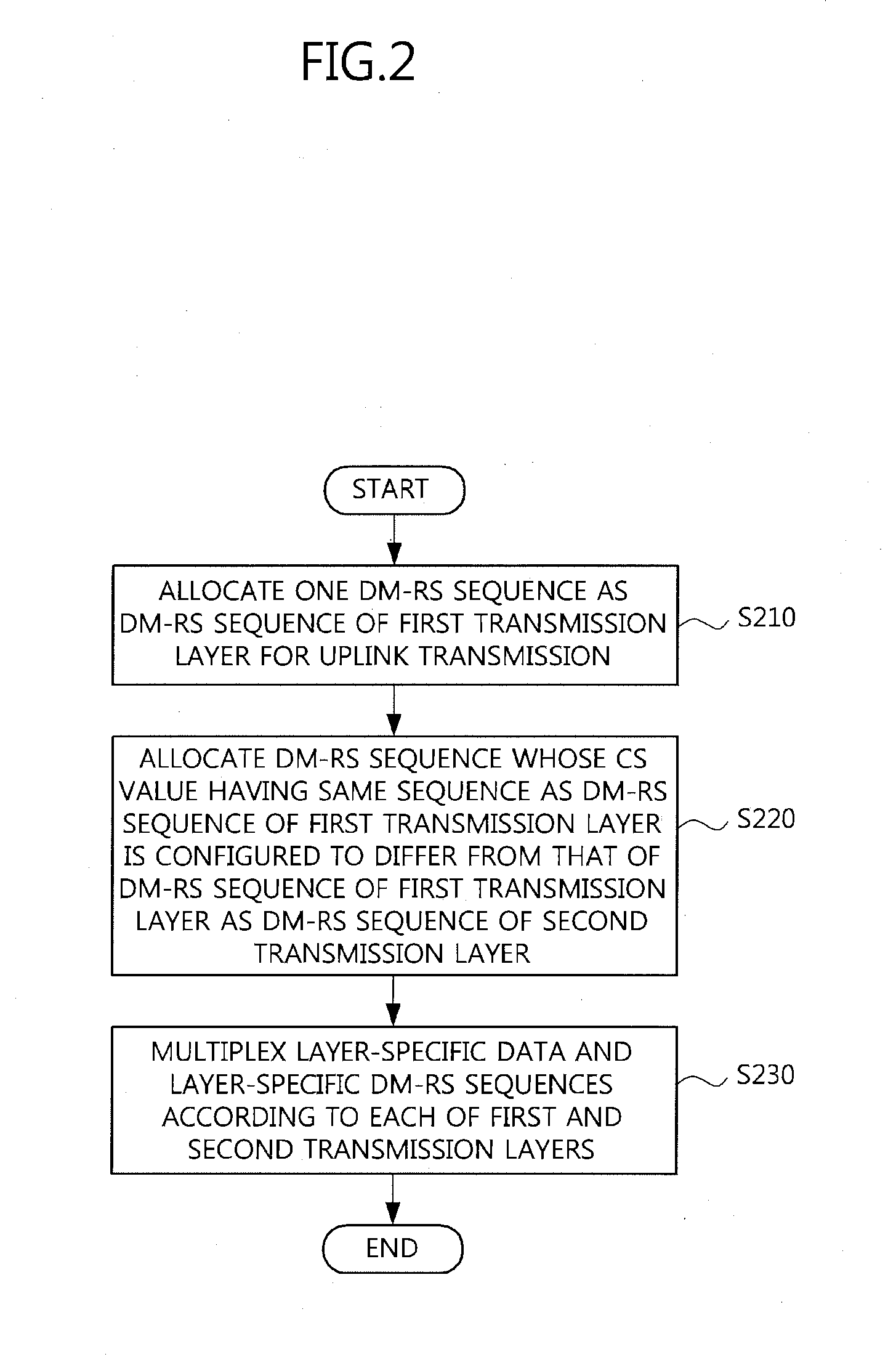
Provided is a multi-layer transmission method of multiplexing and transmitting data and a demodulation reference signal (DM-RS) sequence in an uplink digital Fourier transform-spread-orthogonal frequency division multiplexing (DFT-S-OFDM) transmission employing multiple-input multiple-output (MIMO). The method includes allocating one DM-RS sequence as a DM-RS sequence of a first transmission layer for uplink transmission; allocating a DM-RS sequence whose cyclic shift (CS) value having the same sequence as the DM-RS sequence of the first transmission layer is configured to differ from that of the DM-RS sequence as a DM-RS sequence of a second transmission layer; and multiplexing layer-specific data and the layer-specific DM-RS sequences according to each of the first and second transmission layers. Accordingly, an RS can be transmitted in more OFDM symbols of a slot or subframe without an increase in overhead. Consequently, it is possible to satisfy requirements of LTE-advanced that a high frequency spectrum and a high mobile velocity should be supported, and transmit and receive a DM-RS multiplexed with data while maintaining orthogonality.

Description

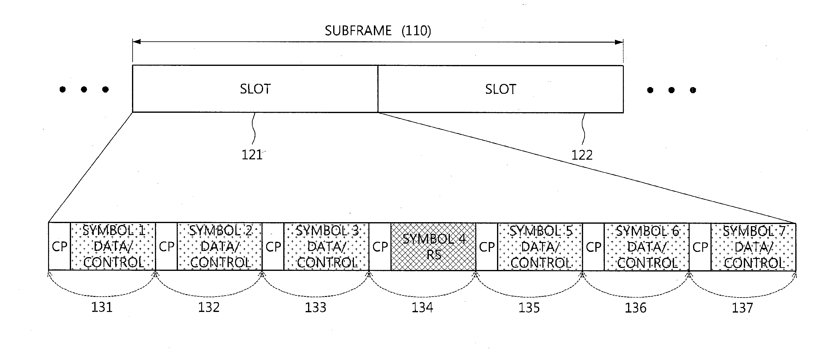
CLAIM FOR PRIORITY[0001]This application claims priority to Korean Patent Applications No. 2010-0005014 filed on Jan. 20, 2010 and No. 2011-0002634 filed on Jan. 11, 2011 in the Korean Intellectual Property Office (KIPO), the entire contents of which are hereby incorporated by reference.BACKGROUND[0002]1. Technical Field[0003]Example embodiments of the present invention relate in general to uplink demodulation reference signal (DM-RS) transmission, and more particularly, to a transmission method of multiplexing data and a DM-RS in one orthogonal frequency division multiplexing (OFDM) symbol while maintaining a low cubic metric (CM) and enabling multi-layer transmission of the multiplexed data and DM-RS in a digital Fourier transform (DFT)-spread (S)-OFDM technique, which is an uplink access scheme of 3rd Generation Partnership Project (3GPP) long term evolution (LTE)-advanced.[0004]2. Related Art[0005]The DFT-S-OFDM technique can efficiently make use of a power amplifier due to an e...

Claims


Application Information

Patent Timeline
Patent Type & Authority Applications(United States)
IPC IPC(8): H04B7/02
CPCH04B7/0413H04L5/0048H04L5/0044H04L5/0023
Inventor JEONG, BYUNG JANGSEO, BANGWONKO, YOUNG JO
Owner ELECTRONICS & TELECOMM RES INST
Why Eureka
Try Eureka