Image forming apparatus
- Summary
- Abstract
- Description
- Claims
- Application Information
AI Technical Summary
Benefits of technology
Problems solved by technology
Method used
Image

Examples
first embodiment
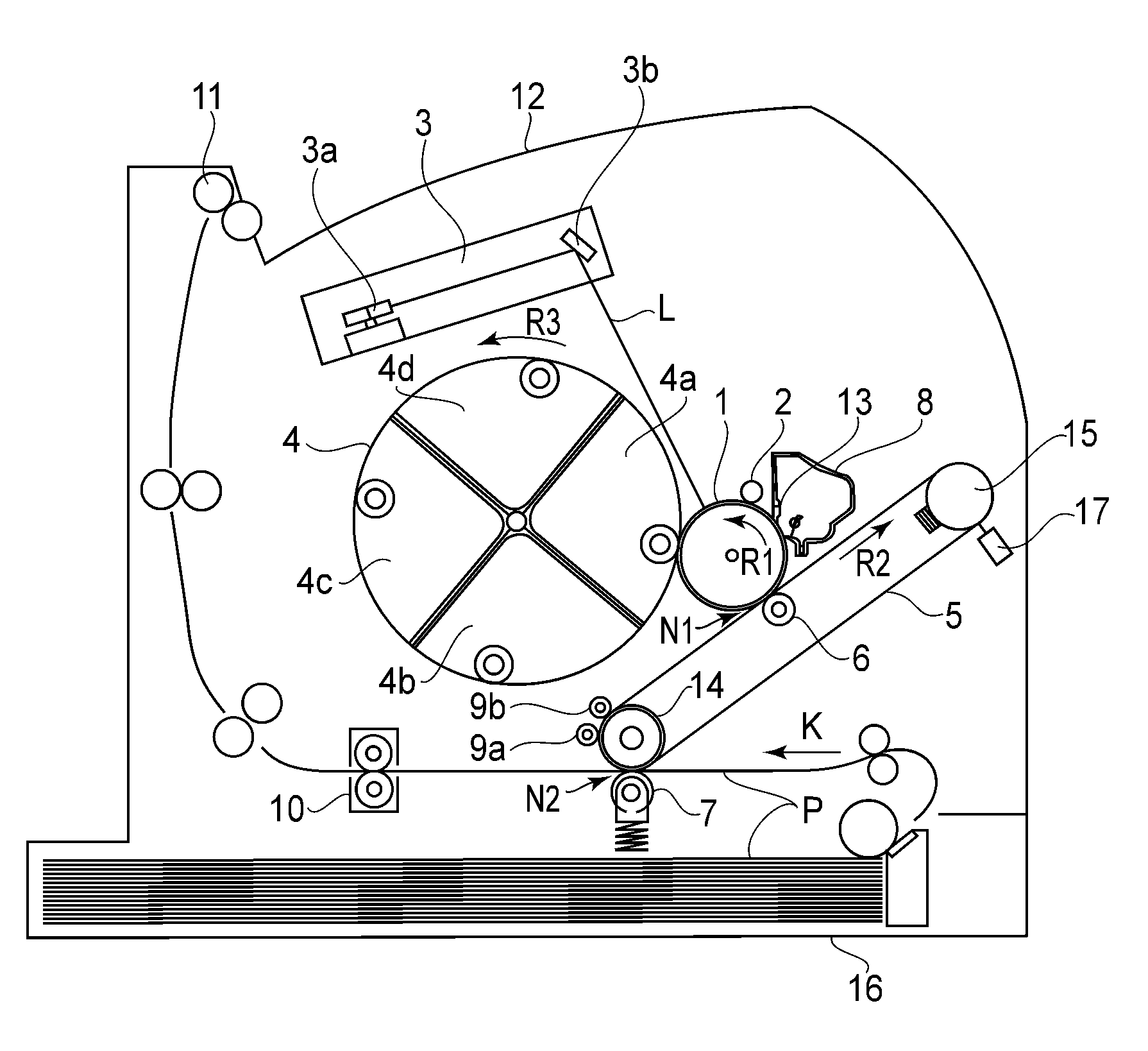
[0029]FIG. 1 is a schematic illustration of an image forming apparatus in this embodiment. The image forming apparatus shown in FIG. 1 is a full-color laser beam printer of an electrophotographic type in which an intermediary transfer belt is used as an intermediary transfer member.
[0030]The image forming apparatus includes a drum-type electrophotographic photosensitive member (hereinafter referred to as a photosensitive drum) 1 as an image bearing member. The photosensitive drum 1 is constituted by providing an electroconductive layer on an outer peripheral surface of an aluminum cylinder. The photosensitive drum 1 is rotatably supported by a main assembly of the image forming apparatus (hereinafter referred to as an apparatus main assembly) and is rotationally driven in a direction indicated by an arrow R1 by an unshown driving unit. A charging roller 2, an exposure unit 3, a developing unit 4, an intermediary transfer belt 5, a photosensitive drum cleaning blade 13 and a residual...
second embodiment
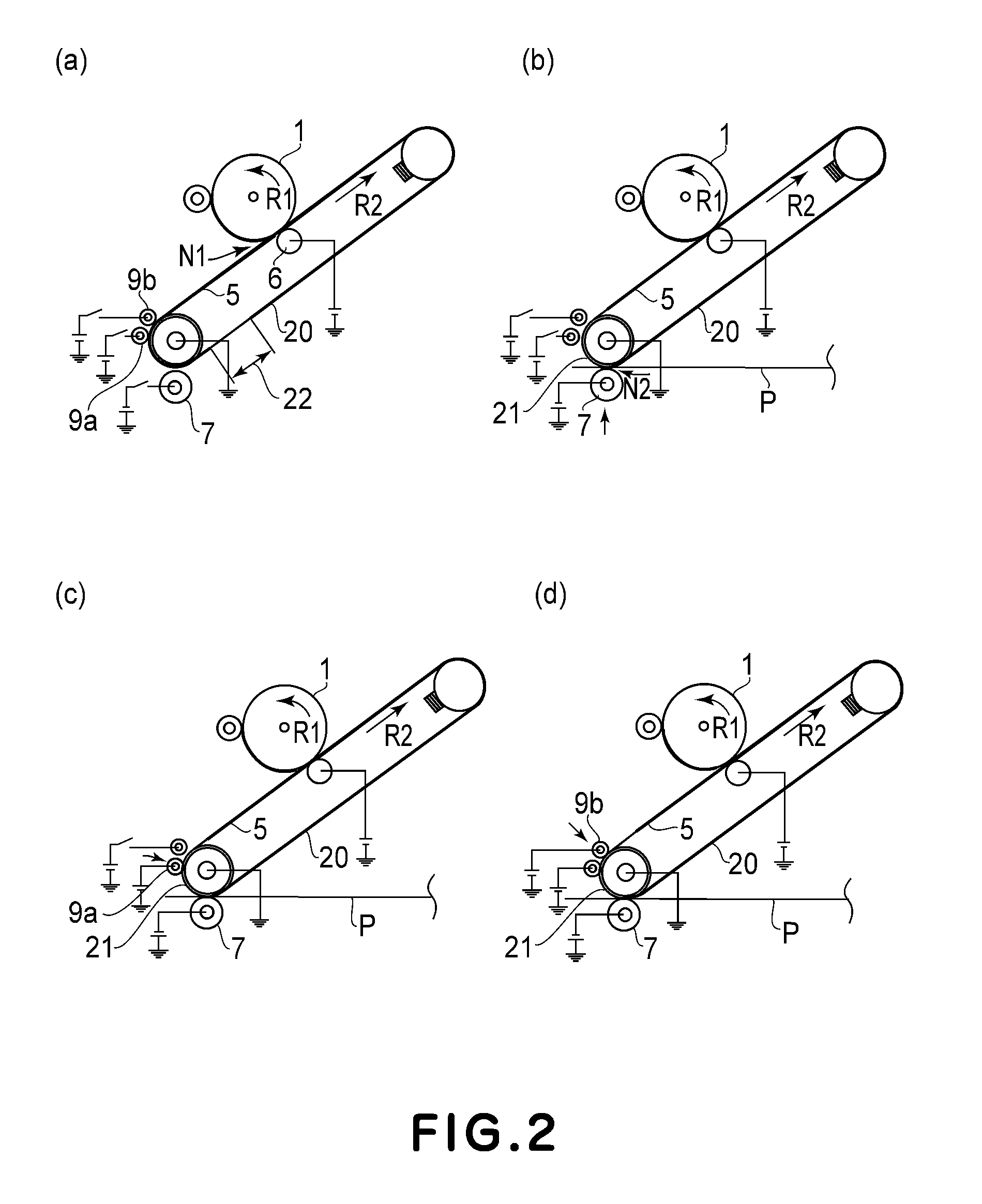
(Contact and Separation Operation of Roller Charger)
[0061]In this embodiment, a basic portion of a constitution of an image forming apparatus is the substantially same as that in First Embodiment. Therefore, the same portion will be omitted from description and a different portion will be described.
[0062]A contact and separation operation, of the roller chargers 9a and 9b, which is a characteristic feature of the present invention will be described with reference to FIGS. 7 and 8.
[0063]Parts (a) to (d) of FIG. 7 are schematic views for illustrating a process from the start of the secondary transfer until the roller chargers 9a and 9b are moved from the separation positions to the contact portions. Referring to FIG. 7, an image transfer area 30 in which the superposed toner images of four colors were formed on the intermediary transfer belt 5, and a non-image transfer area 32 are shown.
[0064]In a stage shown in (a) of FIG. 7, in the primary transfer nip N1, the fourth color toner ima...
PUM
 Abstract
Description
Claims
Application Information
 - Generate Ideas
- Intellectual Property
- Life Sciences
- Materials
- Tech Scout
- Unparalleled Data Quality
- Higher Quality Content
- 60% Fewer Hallucinations
Browse by: Latest US Patents, China's latest patents, Technical Efficacy Thesaurus, Application Domain, Technology Topic, Popular Technical Reports.
© 2025 PatSnap. All rights reserved.Legal|Privacy policy|Modern Slavery Act Transparency Statement|Sitemap|About US| Contact US: help@patsnap.com