Vacuum processing apparatus

Active Publication Date: 2011-07-21
HITACHI HIGH-TECH CORP
View PDF9 Cites 6 Cited by
  • Summary
  • Abstract
  • Description
  • Claims
  • Application Information

AI Technical Summary

Benefits of technology

[0009]Further, the parts arranged in the processing chamber of the vacuum processing apparatus have been mainly formed of a specified material such as aluminum. In recent years, however, the stainless steel material electropolished has come to be employed to reduce CoC (cost of consumer) and thus lengthen the service life of the parts.

Problems solved by technology

The related art described above, however, poses the problem as it fails to take the following points into sufficient consideration.
The related art described above fails to take this problem into consideration.
In recent years, however, the stainless steel material electropolished has come to be

Method used


Image

  • Vacuum processing apparatus
  • Vacuum processing apparatus
  • Vacuum processing apparatus

Examples


embodiments

[0026]With reference to FIGS. 1 to 10, embodiments of the invention are described in detail.

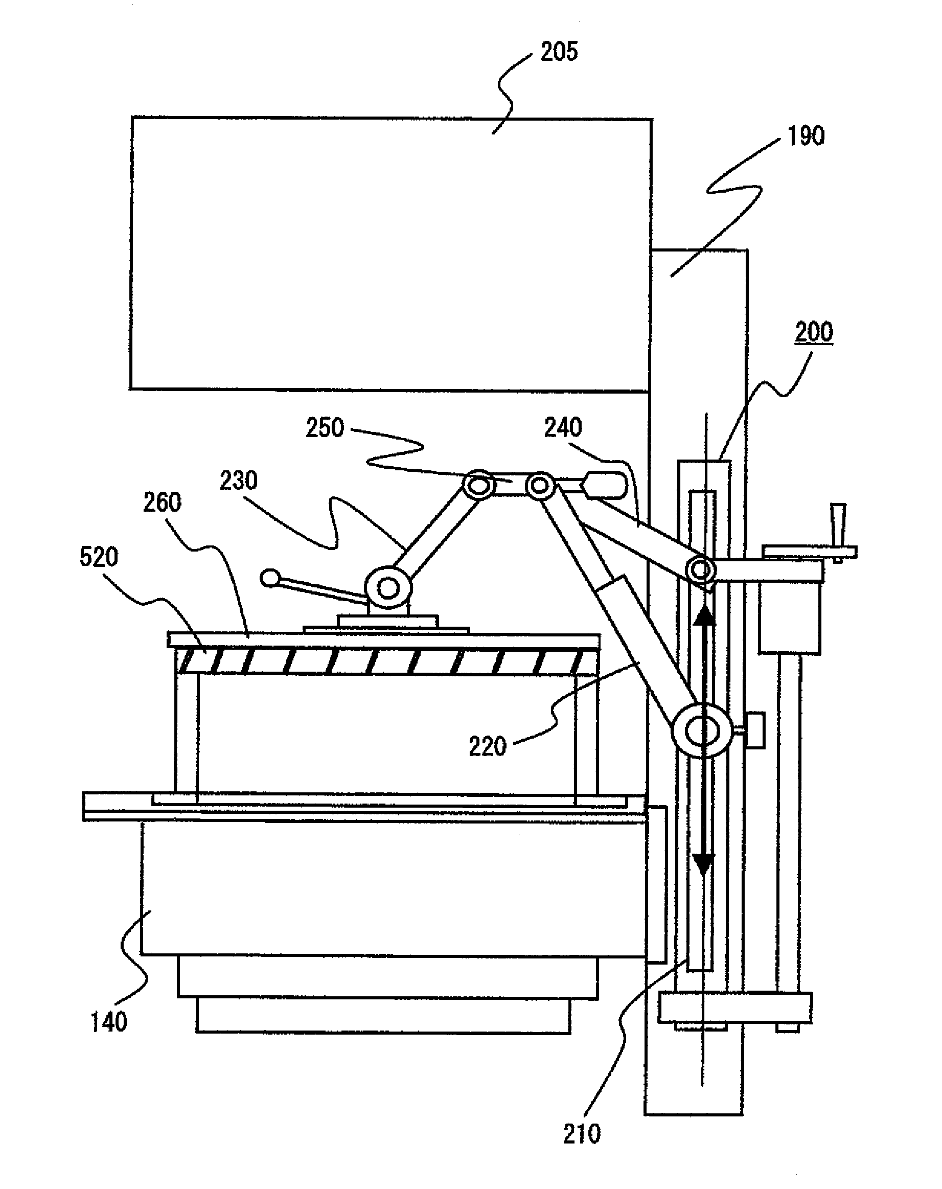
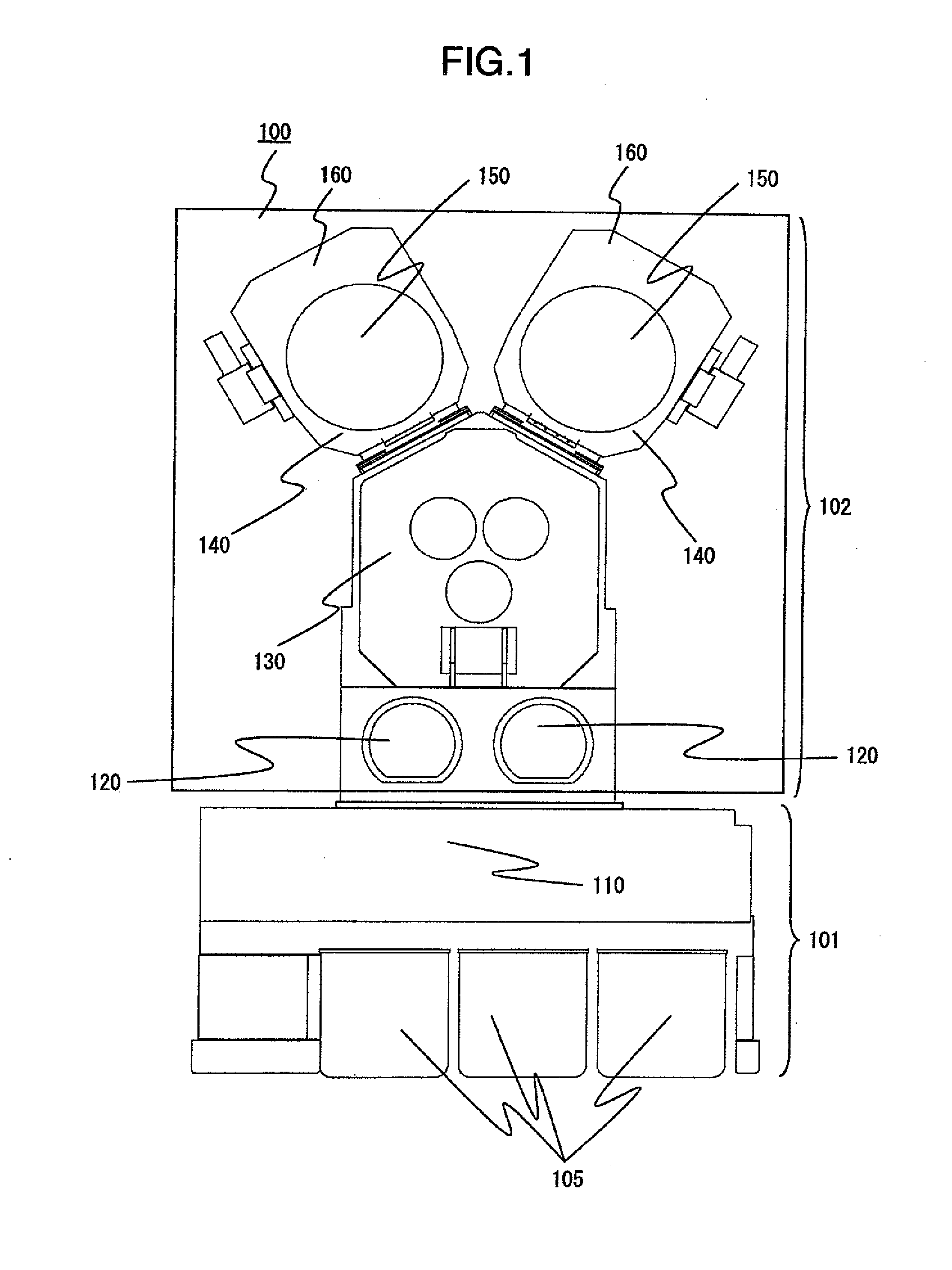
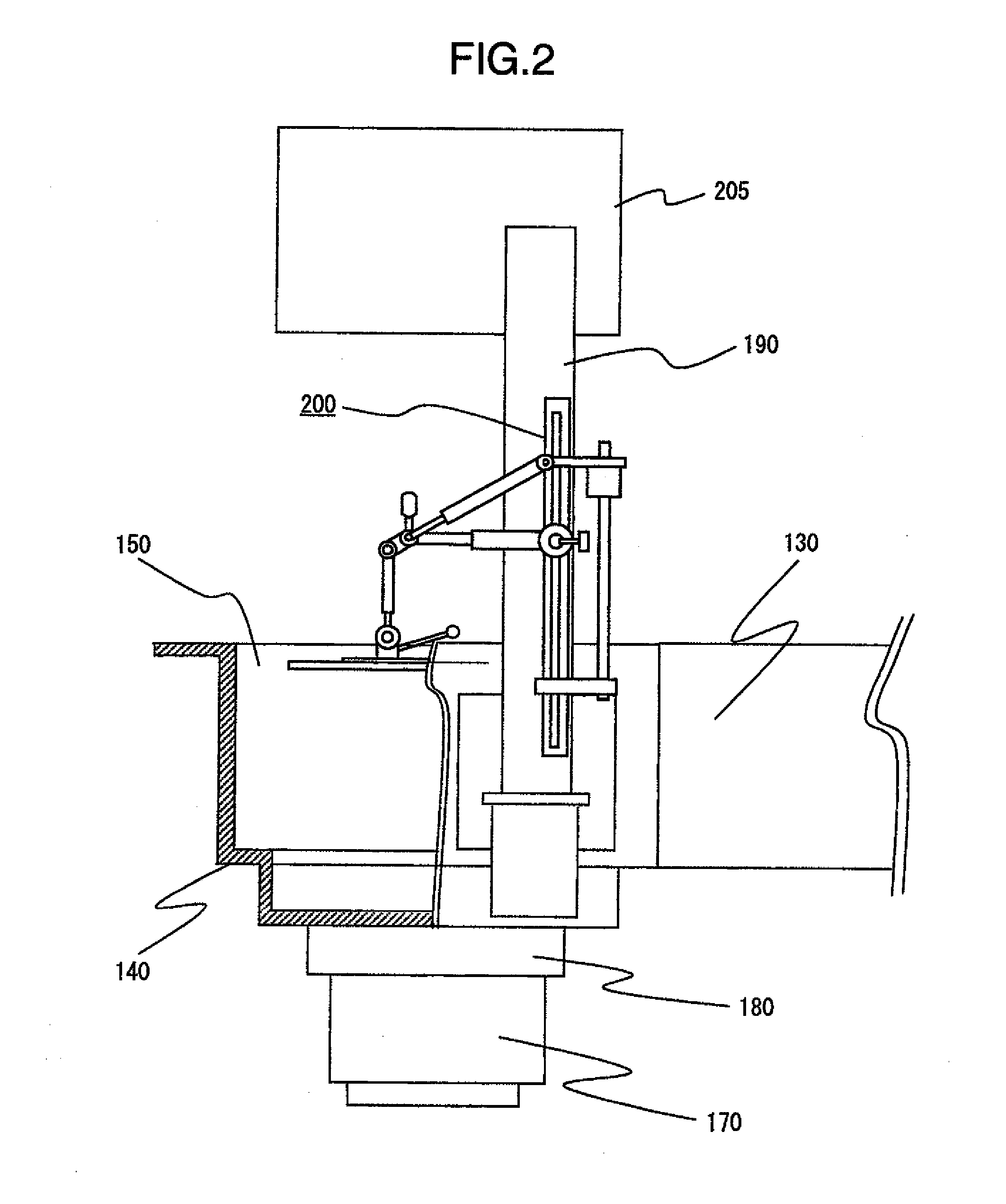
[0027]FIG. 1 is a top plan view schematically showing the configuration of the vacuum processing apparatus according to this invention. The vacuum processing apparatus 100 shown in FIG. 1 is roughly divided into two sections in longitudinal direction. The upper section of FIG. 1 represents the rear side, and the lower section thereof the front side of the vacuum processing apparatus 100. An atmospheric processing section 101 is arranged on the front side and a vacuum processing section 102 coupled to the back of the atmospheric processing section 101 is arranged on the rear side of the vacuum processing apparatus 100.

[0028]The front side of the atmospheric processing section 101 faces a path of a building such as a clean room installed with the vacuum processing apparatus 100. This path is for transferring a cassette accommodating therein a sample on a substrate such as a semiconductor wafer ...


PUM


Abstract

A vacuum processing apparatus includes a transfer container for transferring a wafer in the internal space thereof reduced in pressure, a vacuum vessel coupled to the side wall of the vacuum vessel and including a processing chamber having a sample stage therein on which a wafer to be processed is mounted, a lid member opened or closed by rotation above the vacuum vessel, an inner chamber member arranged in the vacuum vessel and making up the inner wall of the processing chamber, and a jig coupled to the side wall of the vacuum vessel to lift and hold the inner chamber member by being coupled thereto. The jig includes a first joint portion having vertical and horizontal shafts, an extensible arm portion rotatable around each shaft of the first joint portion, and a second joint portion with the inner chamber member adapted to rotate around the horizontal axis thereof.

Description

BACKGROUND OF THE INVENTION[0001]This invention relates to a vacuum processing apparatus for processing a substrate-like sample such as a semiconductor wafer in a processing chamber arranged in a vacuum vessel, or in particular, to a vacuum processing apparatus having a jig for retrieving the members of the processing chamber from the vacuum vessel.[0002]Each vacuum processing apparatus for processing a semiconductor wafer to manufacture a semiconductor device is required to occupy a smaller area to increase the number thereof installed in a building like a cleaning room in which a production line is installed. For this reason, efforts are made to reduce the apparatus size, which in turn makes it necessary to reduce the space for maintenance and inspection of the apparatus as far as possible.[0003]With the increase in the size of the semiconductor wafer, on the other hand, the parts in the vacuum vessel making up the processing apparatus, or especially, the parts of the processing c...

Claims


Application Information

Patent Timeline
IPC IPC(8): H01L21/673H01L21/677
CPCH01L21/67772H01L21/67766
Inventor NAKAMURA, TSUTOMUTANIMURA, HIDENOBUMIZOBE, YUYA
Owner HITACHI HIGH-TECH CORP
Why Eureka
Try Eureka