
Image capture apparatus and zooming method

a technology of zooming and image capture, applied in the field of moving image capture apparatus, can solve the problems of flicker, inability to accurately detect flicker, and inability to detect flicker, and achieve the effect of accurate detection of flicker

Active Publication Date: 2011-07-28
CANON KK
View PDF8 Cites 22 Cited by
  • Summary
  • Abstract
  • Description
  • Claims
  • Application Information

AI Technical Summary

Benefits of technology

[0008]It is desirable to solve the above problem and to allow the accurate detection of a flicker even upon zooming.

Problems solved by technology

The problem of flicker also arises when zooming is performed in this way, namely by reading out a specific region that is a sub-region of the maximum input object image receivable by the image sensor.
If the composition does change significantly, flicker detection may be impossible.
In particular, upon zooming in by reading out a specific (sub-)region, the composition often changes because of the influence of a camera shake, and accurate flicker detection may be impossible.

Method used


Image

  • Image capture apparatus and zooming method
  • Image capture apparatus and zooming method
  • Image capture apparatus and zooming method

Examples


Embodiment Construction

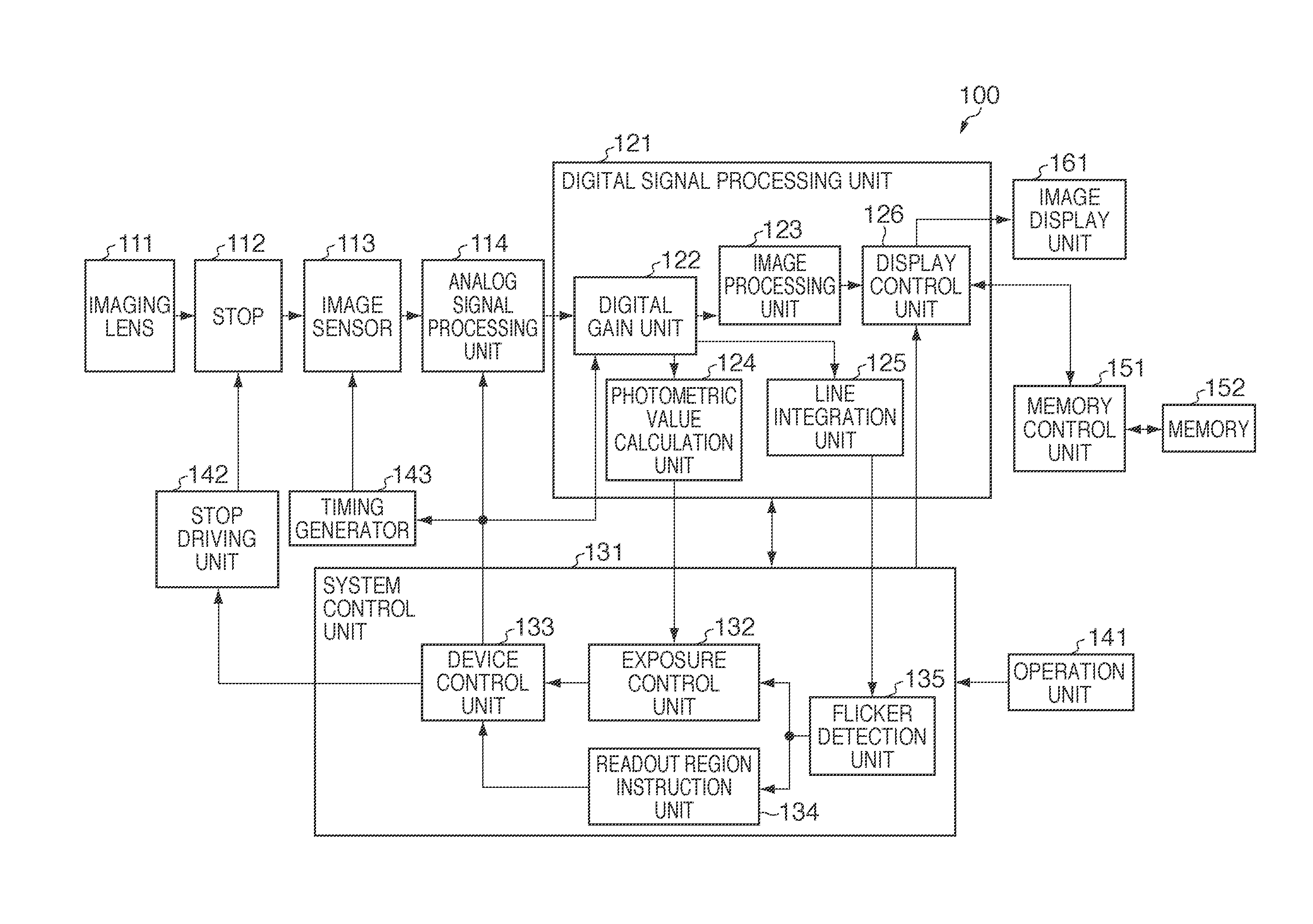
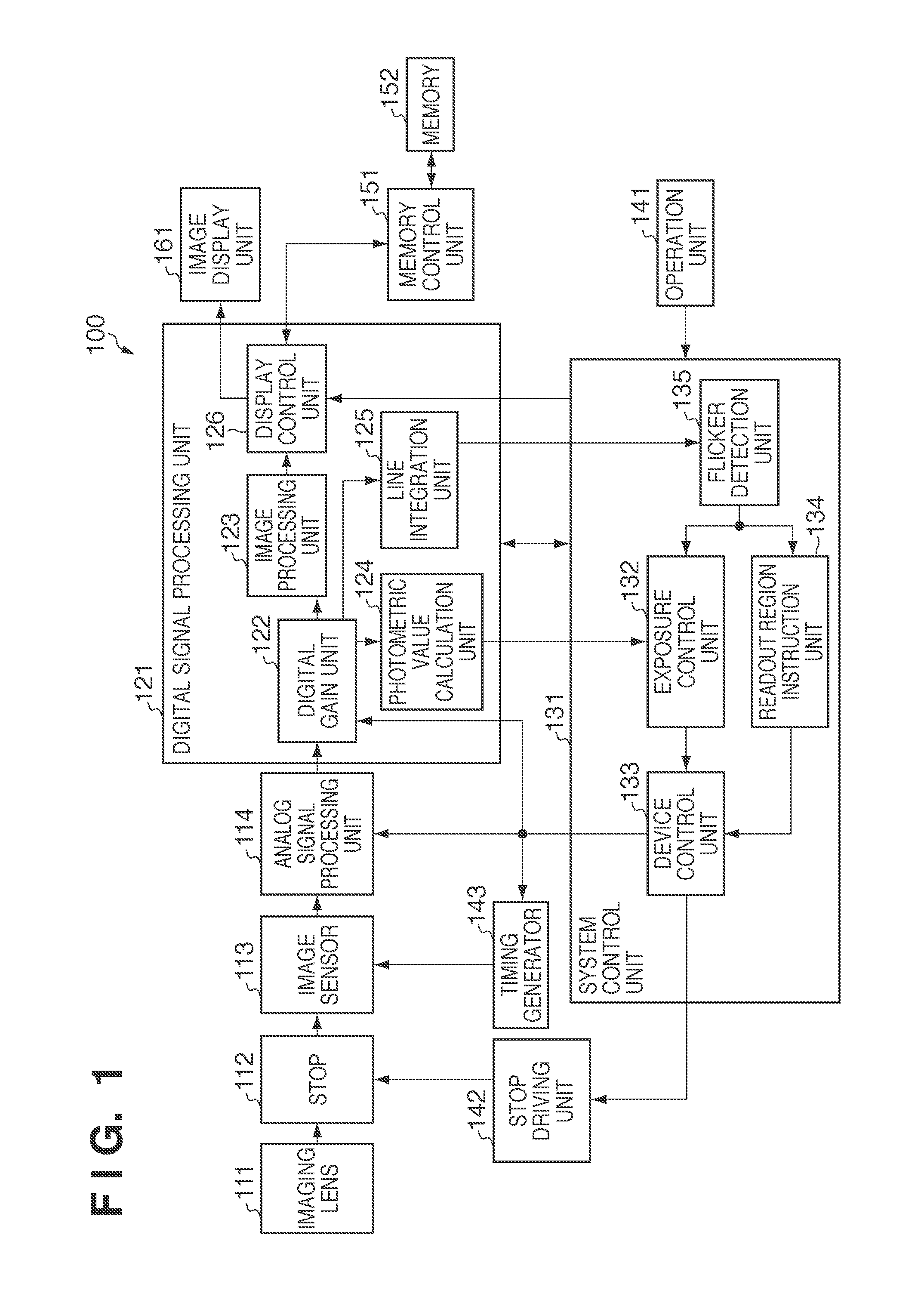
[0016]FIG. 1 is a block diagram showing the arrangement of an image capture apparatus according to an embodiment of the present invention. An image capture apparatus 100 according to the embodiment of the present invention will be described with reference to FIG. 1.

[0017]Referring to FIG. 1, a light beam that has entered an imaging lens 111 forms an optical image on an image sensor 113 via a stop 112. The stop 112 is driven based on a signal output from a stop driving unit 142. The stop driving unit 142 outputs a stop driving amount to the stop 112 under the control of a device control unit 133 in a system control unit 131.

[0018]The image sensor 113 is, for example, an X-Y address scan type CMOS sensor which is driven based on a timing signal output from a timing generator 143 so as to photoelectrically convert an object image into an analog electric signal. The timing generator 143 outputs the timing signal for controlling the electronic shutter to the image sensor 113 upon receivi...


PUM


Abstract

An image capture apparatus comprises an X-Y address scan type image sensor; a flicker detector configured to detect a flicker of a light source; a switch configured to switch the image sensor between a first state in which the image sensor is driven by a first driving method which comprises reading out a pixel signal within a range of a first angle of view and a second state in which the image sensor is driven by a second driving method which comprises reading out a pixel signal within a range of a second angle of view narrower than the first driving method; and a controller configured to control the switch so as to drive the image sensor by the first driving method while the flicker detector is detecting the flicker and to drive image sensor by the second driving method when the flicker detector has completed flicker detection.

Description

BACKGROUND OF THE INVENTION[0001]1. Field of the Invention[0002]The present invention relates to an image capture apparatus and, more particularly, to an image capture apparatus for capturing a moving image.[0003]2. Description of the Related Art[0004]As is conventionally known, when an image capture apparatus using a CCD or CMOS sensor captures a moving image under fluorescent light connected to the commercial power supply, the brightness may vary for each frame or light / dark horizontal stripes may be generated in a frame due to blinking of the fluorescent light at the frequency of the commercial power supply. This light / dark variation is called a flicker. The flicker can be reduced by controlling the electronic shutter to a shutter speed of n / 100 seconds (n is a natural number) for a 50-Hz flicker and n / 120 s for a 60-Hz flicker. To obtain the shutter speed capable of reducing the flicker so as to reduce the flicker, it is necessary to obtain the frequency of the flicker. For exam...

Claims


Application Information

Patent Timeline
Patent Type & Authority Applications(United States)
IPC IPC(8): H04N9/73H04N25/00H04N23/75
CPCH04N5/23296H04N5/2357H04N5/2353H04N5/235H04N23/70H04N23/69H04N23/745H04N23/73
Inventor SUGIE, KAZUHIKO
Owner CANON KK
Learn More