Network Node, Network and a Method for Waking Up a Network Node

a network node and network node technology, applied in repeater circuits, high-level techniques, instruments, etc., can solve the problems of low capacity requirements, time periods during the day with high capacity requirements, and not being used all the time, so as to reduce power, increase capacity within a cell, and save energy

Inactive Publication Date: 2011-07-28
NOKIA SOLUTIONS & NETWORKS OY
View PDF3 Cites 29 Cited by
  • Summary
  • Abstract
  • Description
  • Claims
  • Application Information

AI Technical Summary

Benefits of technology

[0083]A user equipment may also reduce a power during a time the user equipment may not be used in order to save energy. Thus, receiving a paging signalling information from a network, may bring a user terminal in an operational mode in order to receive an incoming call for example. By integrating the mobile like device in the network node, this functionality may be used in the network node.
[0084]When a UE is paged by the macro BS, a corresponding network node or H(e)NB may receive a paging message from the macro BS in parallel to the UE. As a result of receiving the paging message from the macro BS the H(e)NB may start its wake-up procedure and the UE may first connect to the macro BS. Later, when the H(e)NB may have become active or may have entered the fully operational state, the macro BS may perform a handover to HeNB. Thus, a cell coverage may be amended or the capacity within a cell may be increased.

Problems solved by technology

Such micro NodeBs or micro base stations in particular may increase the coverage in private homes and thus, may not be used all the time.
This may lead to time periods during the day with a high capacity requirement and to other time periods with low capacity requirements.
Independently whether it may be used or not, a (e)NB, a H(e)NB and / or a relay may generate costs by its power consumption.
In particular a BTS, Base Station or a NodeB may generate a significant OPEX (Operational Expenditures) by its power consumption.
However, a macro Base Station, which may provide more capacity than a micro Base Station, may not be able to serve high capacity demand and data rates at e.g. homes.
A conventional macro Base Station may not be designed for such high data rates or capacity needs.
A base station or NodeB may generate interference and electromagnetic radiation with possible impact to health of human beings.
Switching off the base station may not be a solution to this problem, since during the time a base station may be switched off, a mobile terminal may become unreachable since the terminal, the user terminal or UE may not be able to connect to the base station.

Method used


Image

  • Network Node, Network and a Method for Waking Up a Network Node
  • Network Node, Network and a Method for Waking Up a Network Node
  • Network Node, Network and a Method for Waking Up a Network Node

Examples


Embodiment Construction

[0101]The illustration in the drawings is schematic. In different drawings, similar or identical elements are provided with the same reference numerals.

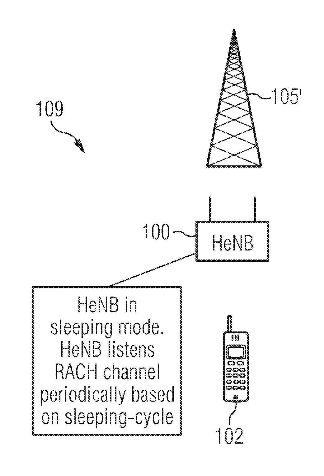
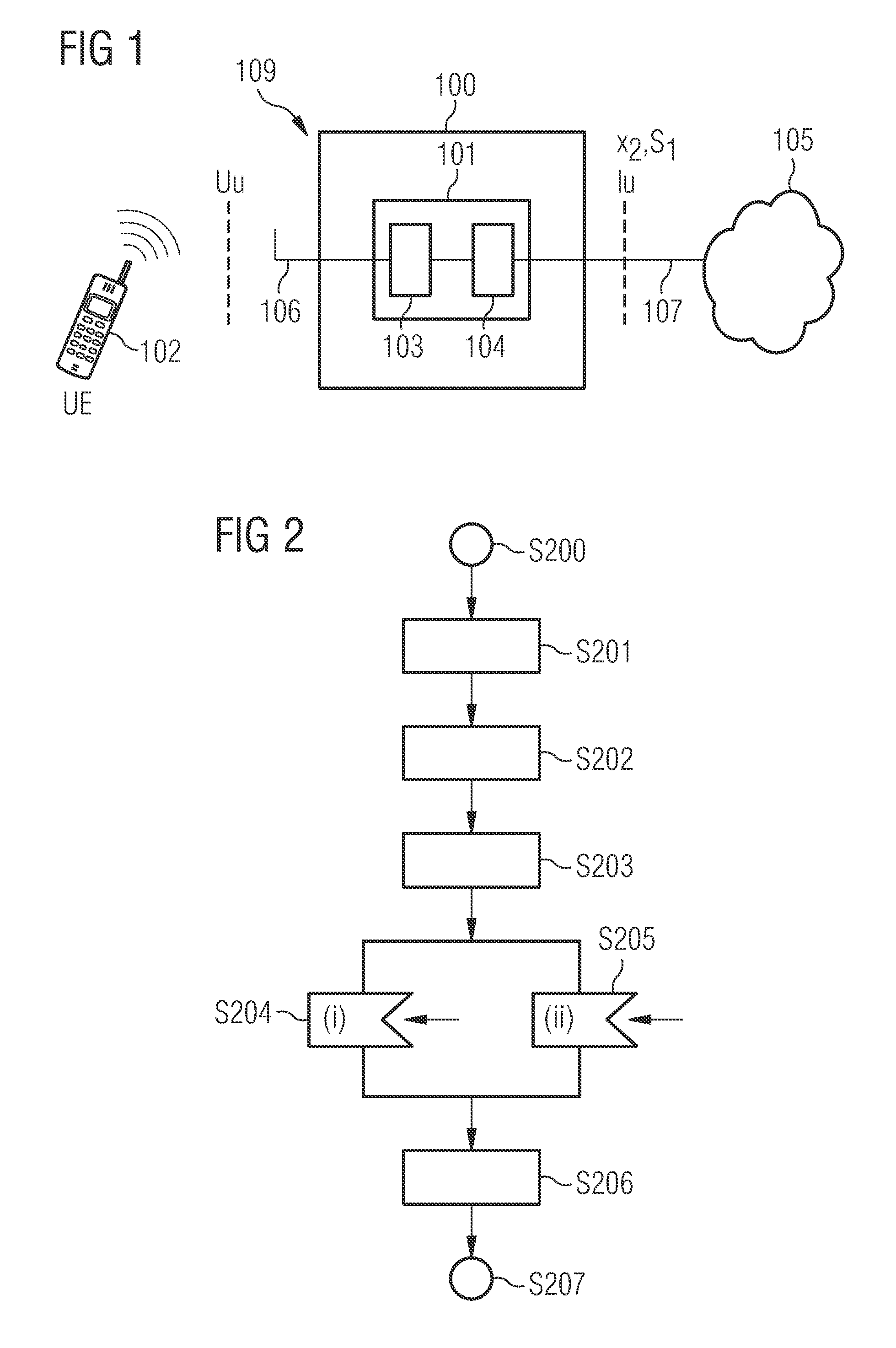
[0102]FIG. 1 shows the UE 102 desiring connection to the network 105. The network node 100 may be a micro BS or H(e)NB and may comprise the sleep control device 101, which comprises the terminal linking device 103 and the network linking device 104. The terminal linking device 103 further comprises the antenna 106 which allows the user equipment UE, 102 to connect to the network node 100 via the air interface Uu.

[0103]The sleep control device 101 further comprises the network linking device 104 which allows the network node to connect via link 107 to the network 105 or to the RAN (Radio Access Network). The link 107 may be a X2, a S1 or an Iu interface.

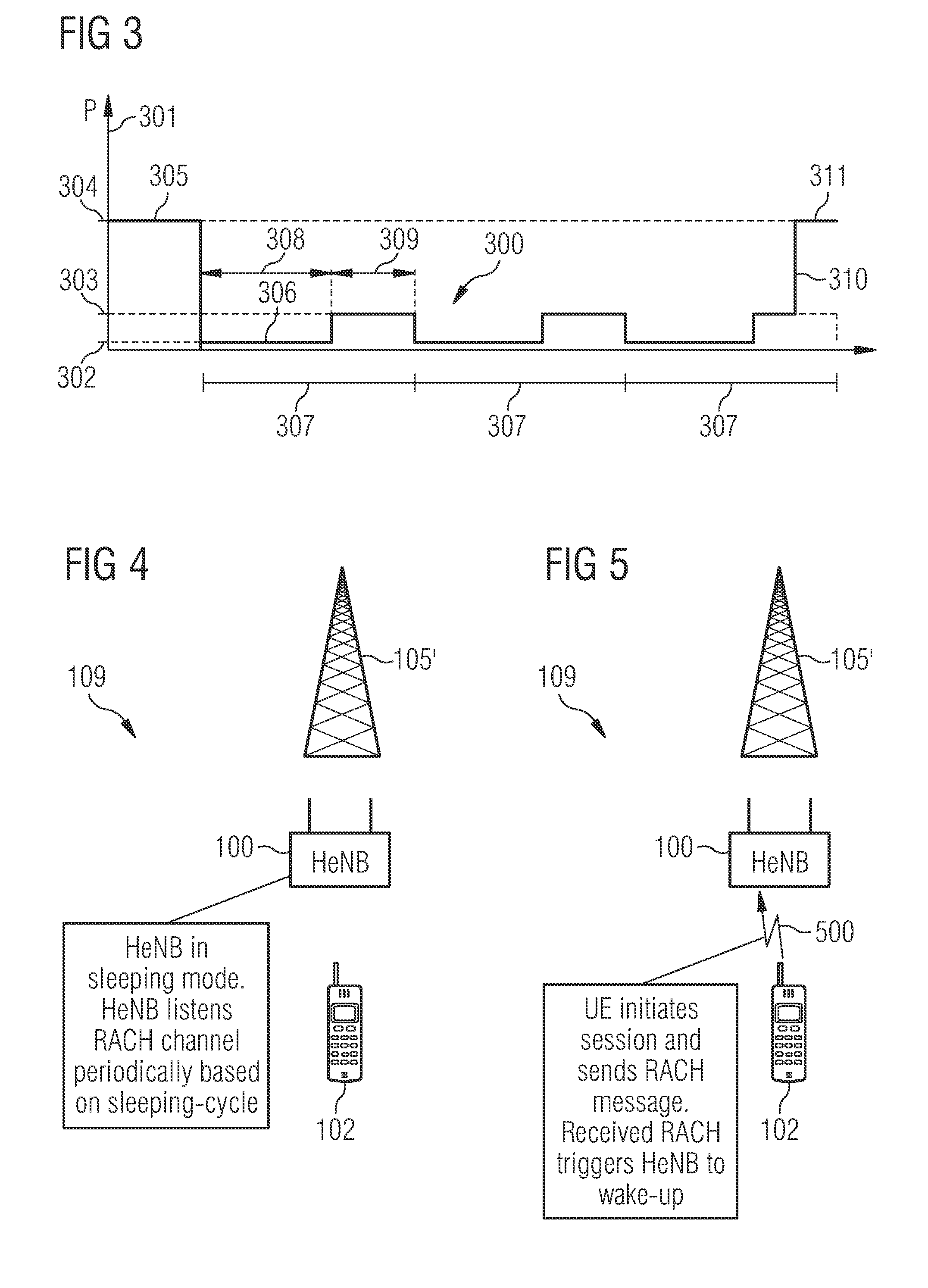
[0104]The network node 100 may be a Home eNodeB 100. This means connectivity for the UE 102 to the network 105 may not have to be provided all the time. For example, during night time ...


PUM


Abstract

A network node for connecting a network with a terminal is described, wherein the network node includes a sleep control device. The sleep control device includes a terminal linking device and a network linking device. The terminal linking device is adapted to connect to a terminal, wherein the network linking device is adapted to connect to a network. Furthermore, the network node is adapted to enter a standby mode, wherein the sleep control device is further adapted to switch on the network node on appearing of at least one trigger event of (i) appearing of a predefined signal sequence on the terminal linking device during a monitoring period of a listen cycle or (ii) appearing of a terminal paging signal sequence on the network linking device. The sleep control device is adapted to detect during the monitoring period the predefined signal sequence on the terminal linking device.

Description

TECHNICAL FIELD OF THE INVENTION[0001]The present invention relates to the technical field of communication networks. In particular the present invention relates to a network node for connecting a network with a terminal, a method for waking up a network node, a program element for waking up a network node, a computer-readable medium for waking up a network node, a use of a paging block cycle for waking up a network node, a network and a network node comprising a terminal type sending device.BACKGROUND OF THE INVENTION[0002]After the roll out of macro cellular mobile communication networks and ensuring a high coverage now ideas may exist to increase the coverage with micro cellular base stations, micro NodeBs, Home NodeBs (HNB, home NB) and Home evolved NodeBs (H(e)NB). Such micro NodeBs or micro base stations in particular may increase the coverage in private homes and thus, may not be used all the time.[0003]Thus, during a day a variable traffic shape may exist in the network. Thi...

Claims


Application Information

Patent Timeline
Patent Type & Authority Applications(United States)
IPC IPC(8): H04B3/36H04W52/02
CPCH04W52/0235H04W52/0206H04W88/08Y02D30/70
Inventor FORSSELL, MIKAHAMALAINEN, SEPPO OLAVIMICHEL, JUERGENTANG, HAITAO
Owner NOKIA SOLUTIONS & NETWORKS OY
Why Eureka
Try Eureka