Heat dissipation fan and rotor thereof

a heat dissipation fan and rotor technology, applied in the field of heat dissipation, can solve the problems of increasing the noise of the heat dissipation fan, limiting the size of the fan blade, and limiting the airflow

Inactive Publication Date: 2011-07-28
FU ZHUN PRECISION IND SHENZHEN +1
View PDF5 Cites 4 Cited by
  • Summary
  • Abstract
  • Description
  • Claims
  • Application Information

AI Technical Summary

Problems solved by technology

Accordingly, the size of the fan blades is limited, which correspondingly limits the airflow.
Thus airflow from the second area to the first area via the gap increases the noise of the heat dissipation fan.

Method used


Image

  • Heat dissipation fan and rotor thereof
  • Heat dissipation fan and rotor thereof
  • Heat dissipation fan and rotor thereof

Examples


Embodiment Construction

Reference will now be made to the drawing figures to describe various embodiments of the present heat dissipation fan in detail.

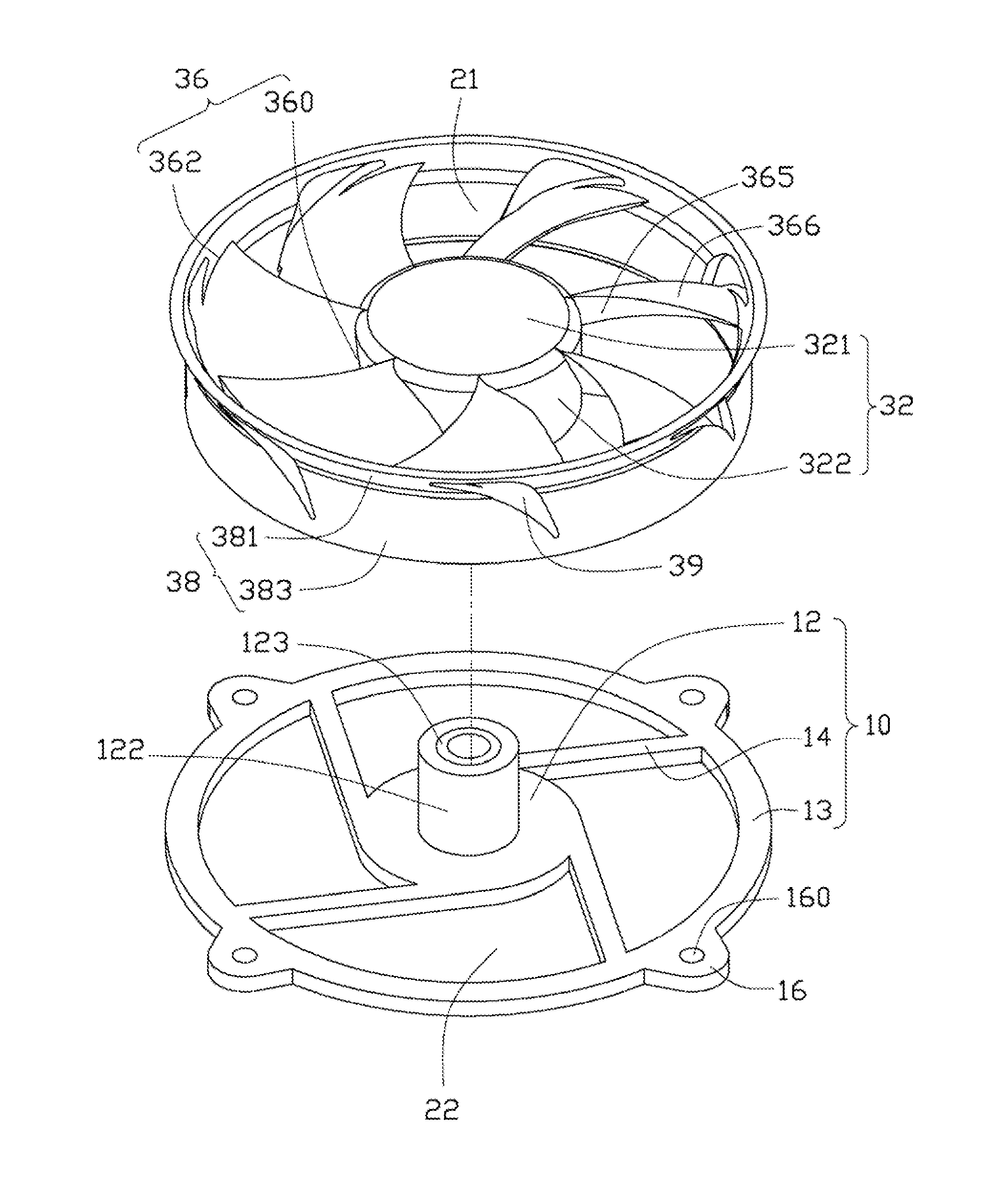
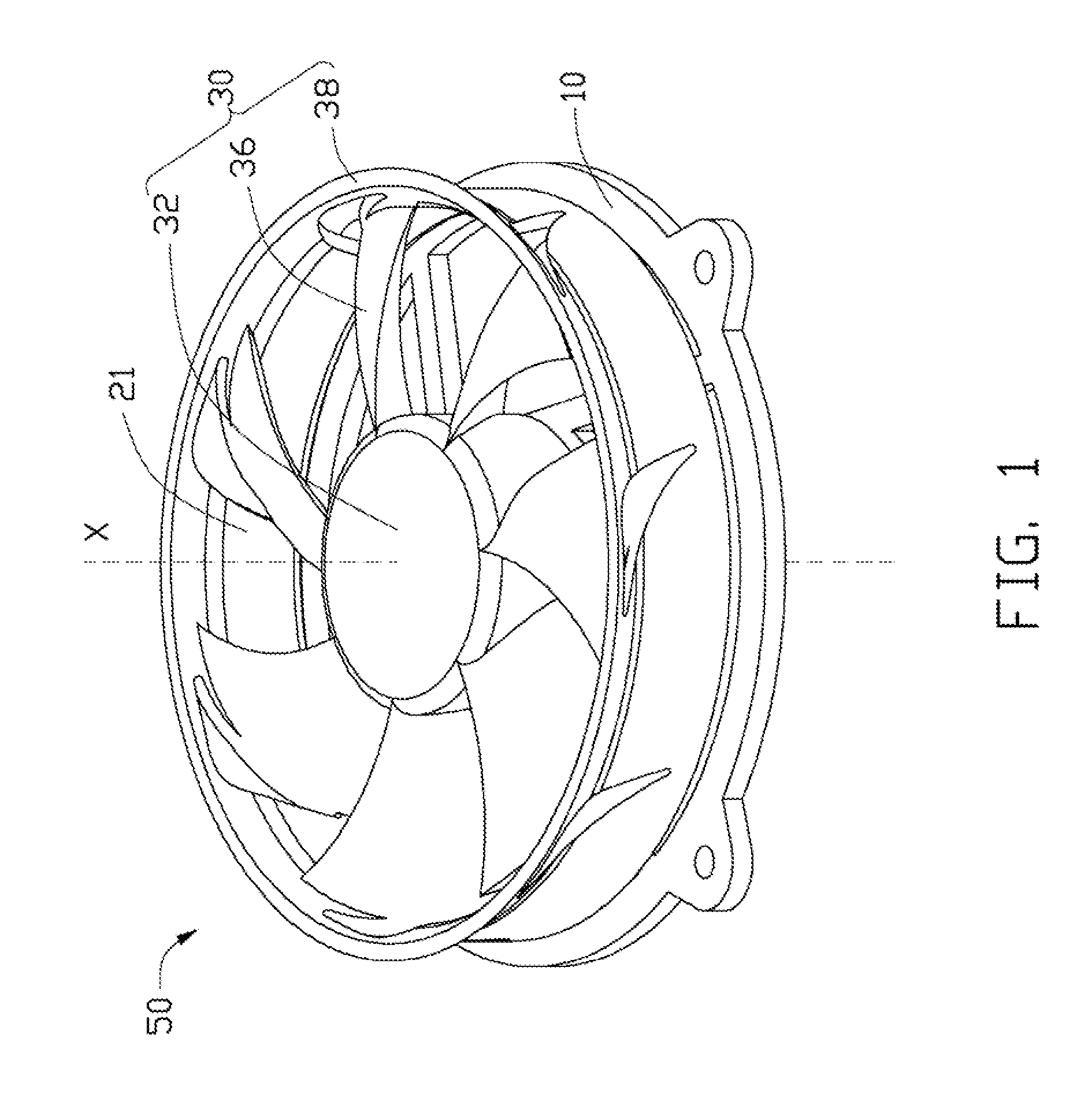
FIG. 1 shows an axial heat dissipation fan 50 according to an exemplary embodiment. A top of the heat dissipation fan 50 forms an air inlet 21 directing airflow into the heat dissipation fan 50, and a bottom of the heat dissipation fan 50 forms an air outlet 22 exhausting airflow from the heat dissipation fan 50.

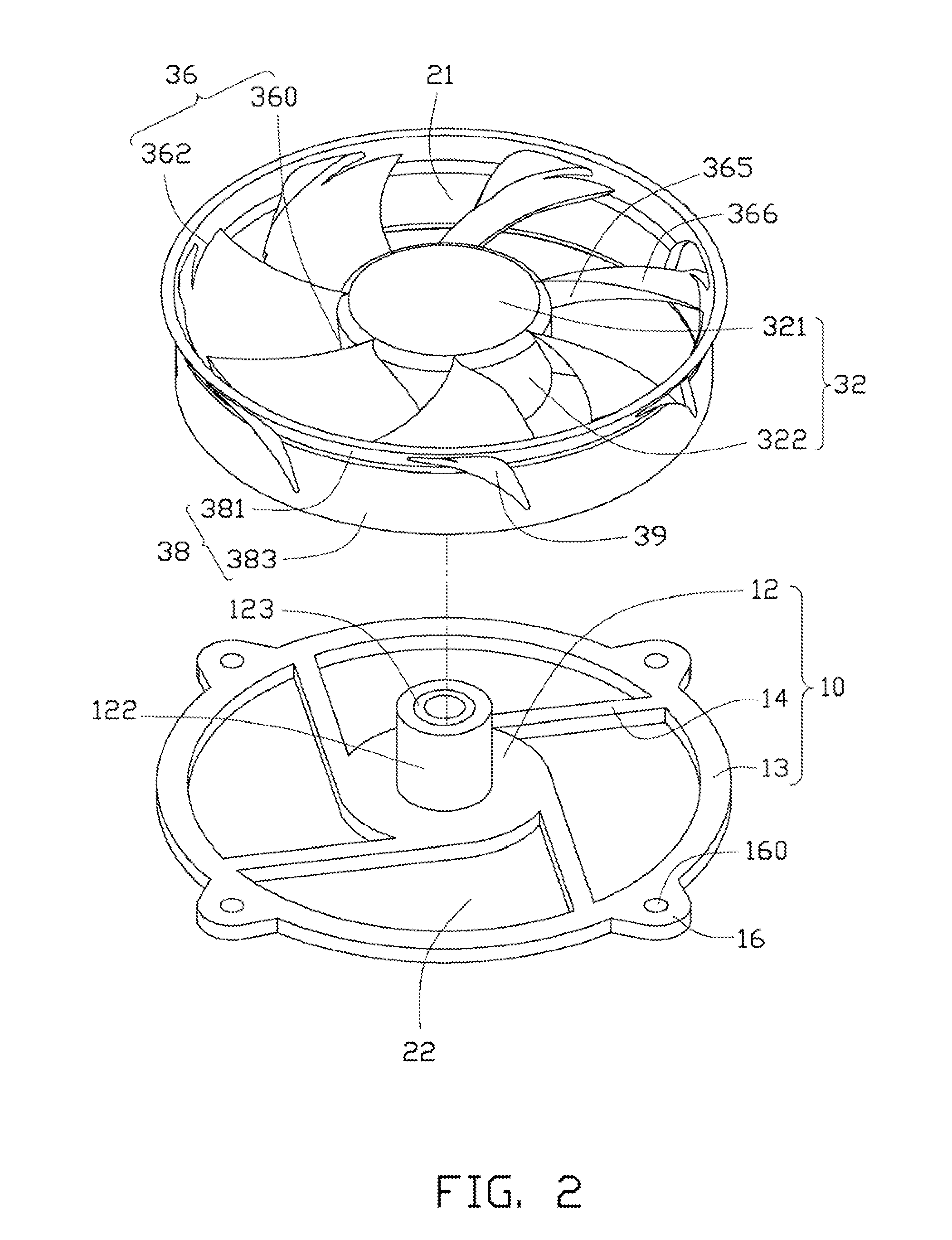
The heat dissipation fan 50 includes a base 10, a stator (not shown), and a rotor 30. Referring also to FIG. 2, the base 10 includes a circular supporting portion 12, an annular fixing portion 13 concentric with and spaced from the supporting portion 12, and a plurality of ribs 14 extending outwardly from an outer periphery of the supporting portion 12 to connect an inner periphery of the fixing portion 13. The air outlet 22 is defined between the supporting portion 12 and the fixing portion 13. The ribs 14 extend from and are evenly arranged along ...


PUM


Abstract

A rotor includes a hub, rotary blades extending outwardly from the hub, and an annular wall surrounding the rotary blades. Each rotary blade includes a windward lateral surface and a leeward lateral surface at opposite sides thereof. The annular wall adjoins the outer ends of the rotary blades and is rotatable therewith. A perforation is defined in the annular wall between two neighboring rotary blades and adjacent to the leeward lateral surface of a leading rotary blade of the neighboring rotary blades.

Description

BACKGROUND1. Technical FieldThe present disclosure relates to heat dissipation, and more particularly to a heat dissipation fan.2. Description of Related ArtHeat dissipation fans are commonly used in combination with heat sinks for cooling electronic devices such as central processing units (CPUs).Often, a heat dissipation fan includes a stator and a rotor. The rotor includes a hub and a plurality of fan blades extending outwardly therefrom. Each of the fan blades includes a windward lateral surface and a leeward lateral surface at opposite sides thereof. A permanent magnet is arranged in the hub and surrounds the stator. The stator includes a stator core with coils wound therearound. When electrical current is supplied to the coils, the fan blades, rotated by interaction of magnetic force of the permanent magnet and magnetic forces of the coils, generate airflow. A fan housing surrounding the stator and the rotor guides the airflow in a desired direction.During operation, while the...

Claims


Application Information

Patent Timeline
Patent Type & Authority Applications(United States)
IPC IPC(8): B63H1/16
CPCF04D25/0613F04D29/681F04D29/384F04D29/164
Inventor ZHA, XIN-XIANGYU, YE-FEIKUO, JER-HAUR
Owner FU ZHUN PRECISION IND SHENZHEN
Why Eureka
Try Eureka