Switching circuit and a method of operation thereof

a switching circuit and switching method technology, applied in the field of switching circuits, can solve the problems of unacceptable lag in the response of the switching circuit, and achieve the effect of reducing power losses and reducing the number of times the switch must be switched

Inactive Publication Date: 2010-04-06
BAE SYSTEMS PLC
View PDF37 Cites 0 Cited by
  • Summary
  • Abstract
  • Description
  • Claims
  • Application Information

AI Technical Summary

Benefits of technology

[0032]Preferably, the method may comprise the step of generating the first and second pulsed switching signals according to a rule that the first and second switches are not switched concurrently. Operating only one switch at a time is advantageous because the voltage drops that occur across the electromagnet may be halved at each switching event. This is particularly advantageous where the voltage drop of 2VS that occurs with the prior art current controller is above or close to the insulation breakdown voltage of the electromagnet. Conversely, adopting bipolar switching allows the bridge circuit to be run from a higher voltage DC source without fear of insulation breakdown upon switching the transistors. Furthermore, the power of the unwanted components in the output waveform at harmonics of the pulse repetition frequency is reduced from a fixed high level to a lower level which drops as the signal drops.
[0033]The method may comprise the step of generating the first and second switching signals according to a rule that the signals are to have no more than one pulse per period. Advantageously, this minimises the number of times the switches must be switched, thereby reducing power losses.

Problems solved by technology

This is particularly useful where delays in the voltage sensor lead to an unacceptable lag in the response of the switching circuit to fluctuations in the DC supply.

Method used


Image

  • Switching circuit and a method of operation thereof
  • Switching circuit and a method of operation thereof
  • Switching circuit and a method of operation thereof

Examples


Embodiment Construction

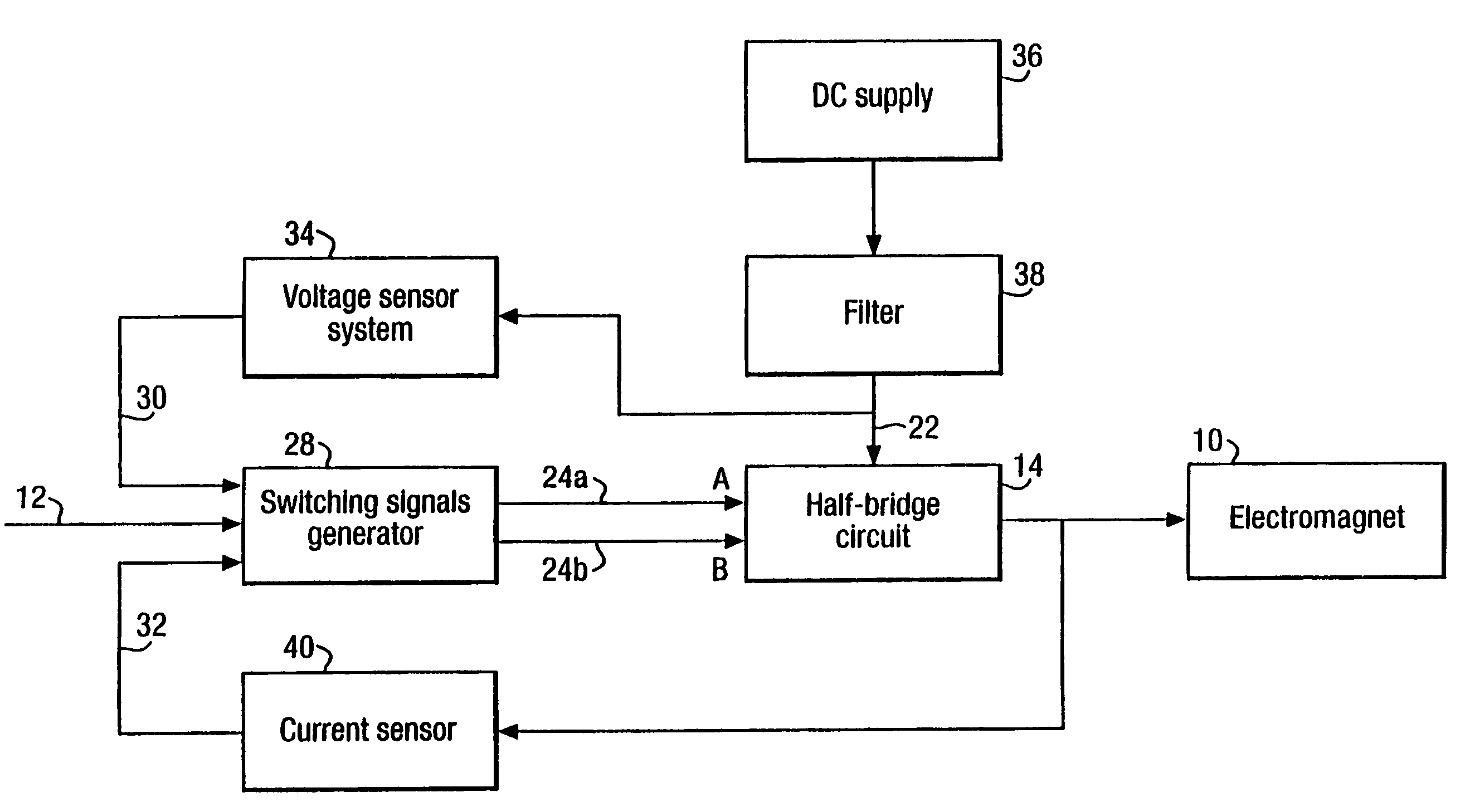
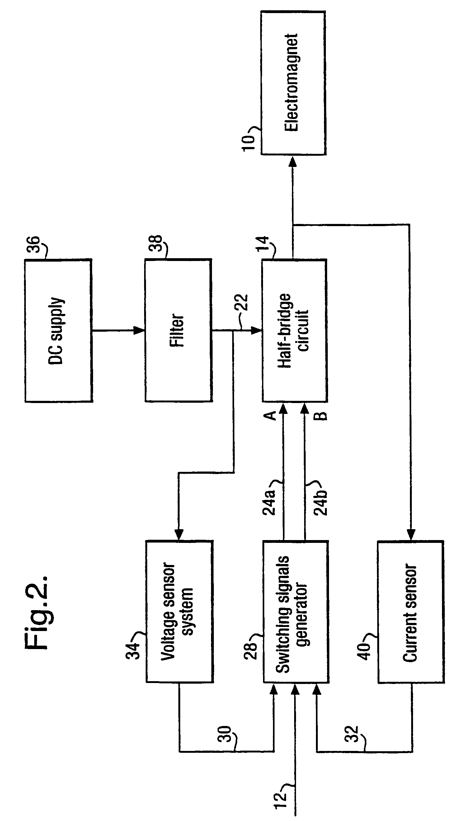
[0050]A current controller that may be operated in accordance with the method of the invention is illustrated in the schematic sketch of FIG. 2. As will be clear, the current controller supplies current to an electromagnet 10. The electromagnet 10 may, for example, be one of an array of such electromagnets used to levitate a raft supporting moving machinery that is subject to resonant vibrations thereby isolating the resonances from any surrounding structure.

[0051]In this embodiment, the current controller supplies electrical current to the electromagnet 10 in response to a voltage demand signal 12. The voltage demand signal 12 is generated in accordance with a desired force to be generated by the electromagnet 10. For example, the voltage demand signal 12 may be generated by a global controller (not shown) that gathers information about the vibrations of the raft supporting the moving machinery from a number of motion sensors over successive periods of time. The global controller m...


PUM


Abstract

This invention relates to a switching circuit, such as a bridge circuit, comprising first and second switches operable to produce an electrical signal at the output of the switching circuit at certain voltages. Moreover, this invention also relates to a method of operating such a switching circuit. The switching circuit comprises an input operable to receive a DC signal of +Vs, an output, first and second switches operable in response to first and second switching signals to be switched between on and off states such that switching between various combinations of on and off states produces an electrical signal at the output with voltage pulses at levels of +Vs, 0V and −VS and a voltage sensor for producing a signal indicative of a voltage offset in the switching circuit. Voltage effects in the switching circuit can be compensated for by using the signal produced by the voltage sensor.

Description

[0001]This application is the US national phase of international application PCT / GB02 / 05733 filed in English on 17 Dec. 2002, which designated the U.S. PCT / GB02 / 05733 claims priority to GB Application No. 0200024.8 filed 2 Jan. 2002. The entire contents of these applications are incorporated herein by reference.BACKGROUND OF THE INVENTION[0002]1. Field of the Invention[0003]This invention relates to a switching circuit comprising first and second switches operable to produce an electrical signal at the output of the switching circuits at certain voltages. Moreover, this invention also relates to a method of operating such a switching circuit.[0004]The switching circuit may comprise a bridge circuit operated to produce a voltage across a load connected to an output of the bridge circuit in accordance with a required voltage. For example, a presently contemplated application of the present invention is in driving an electromagnet in response to a demanded force produced by the electro...

Claims


Application Information

Patent Timeline
Patent Type & Authority Patents(United States)
IPC IPC(8): H01H47/00H01H83/00H02J7/00H02M3/155H02M3/158
CPCH02M3/158
Inventor WESTCOTT, ANDREW M G
Owner BAE SYSTEMS PLC
Why Eureka
Try Eureka