Device for analyzing the step-by-step injection rate provided by a fuel injection system used in a high power heat engine

a fuel injection system and step-by-step technology, which is applied in the direction of instruments, machines/engines, relative volume flow measurement, etc., can solve the problem of slightly complicating the control of the device mode, and achieve the effects of high absolute measuring precision, limited absolute measuring precision, and large absolute measuring precision

Inactive Publication Date: 2011-08-04
EFS SA
View PDF6 Cites 2 Cited by
  • Summary
  • Abstract
  • Description
  • Claims
  • Application Information

AI Technical Summary

Benefits of technology

However, it is advantageous that, among the second measuring chamber and the additional measuring chamber(s), there is at least one measuring chamber with a larger capacity than the others and at least one least one measuring chamber with a smaller capacity than the others, therefore at least two measuring chambers with different capacities and in particular different sections, the electronic section being provided to control one and / or the other of these measuring chambers as a function of the unitary quantities of fuel injected at each step. As will be understood, the measuring chamber with the larger capacity and in particular the larger section has a fairly limited absolute measuring precision, while the measuring chamber with the smaller capacity and in particular the smaller section has a high absolute measuring precision. Thus, the device has a large absolute measuring precision when the injected quantity is small, while keeping the possibility of measuring large injected quantities. The device therefore tends to procure a measurement whereof the relative precision remains substantially constant, which is a desired advantage for any measuring apparatus or device with a high measuring dynamic, i.e. making it possible to precisely measure both small quantities and large quantities. In the case at hand, it is possible to measure very correctly, i.e. with an absolute precision in the vicinity of one thousandth of the maximum scale, injected quantities between 100 mm3 and 100,000 mm3 per injection step.
It will be noted that, owing to its usage principle combined with several variable-volume measuring chambers, the device of the invention makes it possible not only to measure higher injection rates than a variable-volume single-chamber device, but it also makes it possible to measure injection rates for higher injection frequencies, in proportion to the number of implanted measuring chambers.
In other words, the configuration according to the invention is very advantageous due to the fact that, by a simple adaptation of the parameters of the controlling software, it becomes possible to measure higher rates at higher injection frequencies, without constructive modification of the device. This makes the device, subject matter of the invention, particularly well suited to characterize real injection systems which, in fact, inject larger unitary quantities, step by step, at a low rotational regime of the engine and lower unitary quantities, but more frequent ones, as the rotational regime of the engine increases.

Problems solved by technology

This other control mode slightly complicates the controlling of the device, each variable-volume chamber having to be controlled separately; however, it has the advantage of regularizing the flow leaving the first measuring chamber, some of the variable-volume measuring chambers receiving fluid while others are already in the draining process.

Method used


Image

  • Device for analyzing the step-by-step injection rate provided by a fuel injection system used in a high power heat engine
  • Device for analyzing the step-by-step injection rate provided by a fuel injection system used in a high power heat engine

Examples


Embodiment Construction

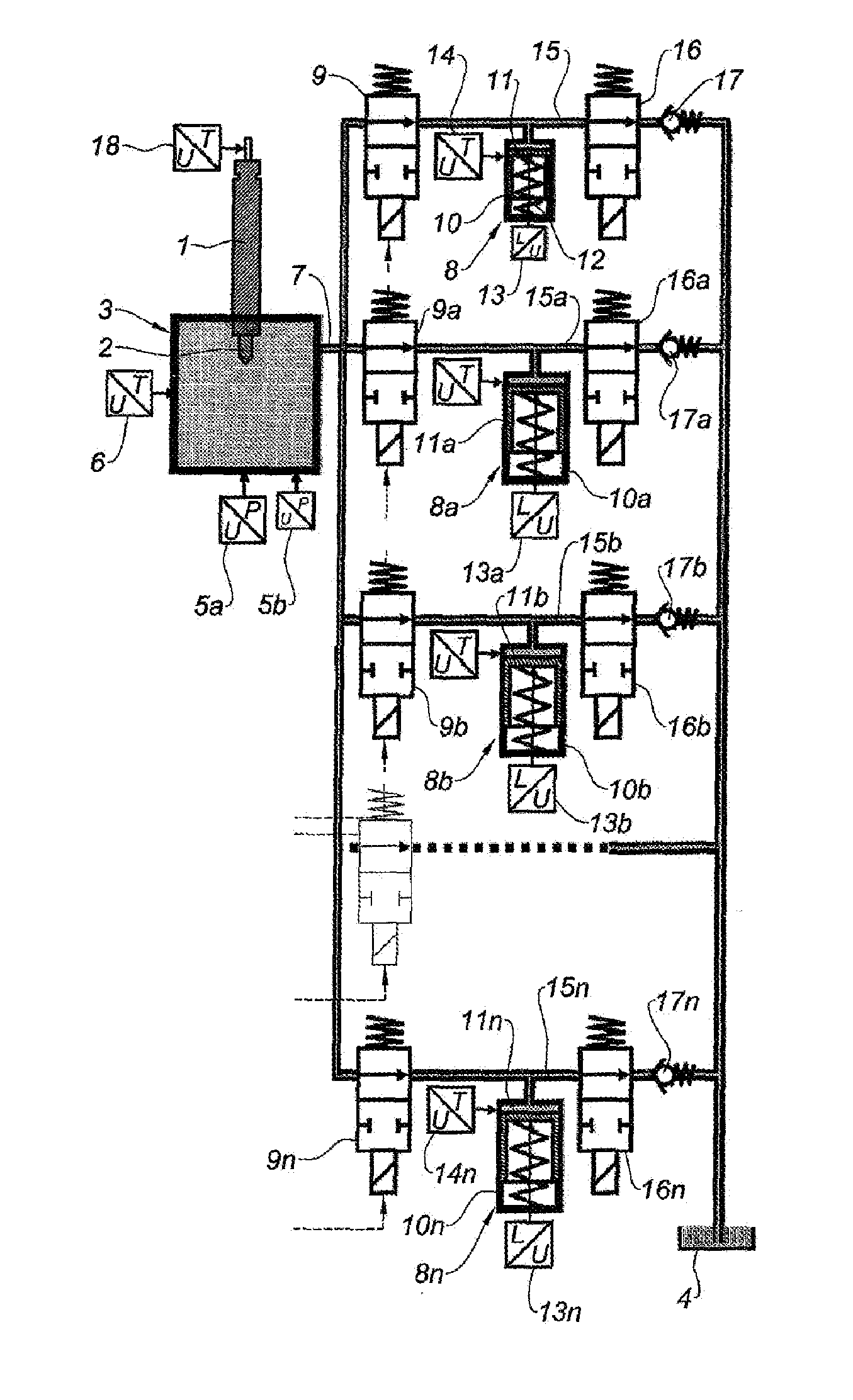
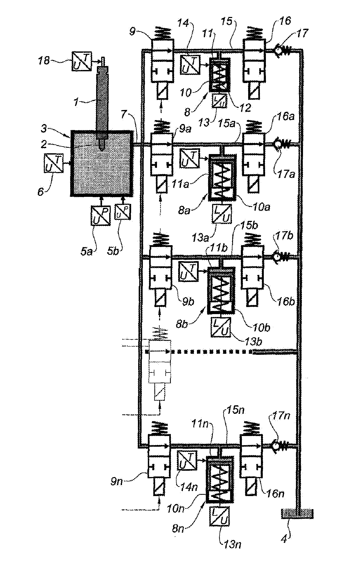
This sole FIGURE shows an injector 1, the injection nozzle 2 of which is in a first measuring chamber 3, which is a constant-volume chamber. The first measuring chamber 3 is, in use, filled with a fluid that has hydraulic characteristics close to those of a fuel, but has a much higher flash point temperature than that of a fuel, in order to minimize the risks of fire and explosion. This fluid is also the fluid used in the injector 1. A reservoir 4 of this fluid is provided in the device.

In the illustrated example, the first measuring chamber 3 advantageously includes, as pressure sensor, a dynamic pressure converter 5a and a static pressure converter 5b. The dynamic pressure converter 5a, which can be made in the form of a piezoelectric converter, is responsible for measuring the dynamic component for which one seeks a high resolution—typically 0.001 bar—and a quick response. The static pressure converter 5b, which can be made in the form of a piezoresistive converter, is responsibl...


PUM


Abstract

The invention relates to a device that includes: a first chamber (3) for measuring a constant volume, and in which the fuel is injected; pressure (5a, 5b) and temperature (6) sensors associated with said first chamber (3); and a second measuring chamber (8) located downstream from the first, into which the fuel drained from the first chamber is sent. The volume of the second chamber (8) varies according to the movement of a piston (11), the movement of which is measured by means of a sensor (13). One or more additional measuring chambers (8a, 8b, . . . 8n) of variable volumes are connected in parallel with the second chamber (8) and also receive the fuel drained from the first chamber (3), the volumes received in said different chambers being added up to obtain the total volume supplied for a single injection step. The device can be used for high injection rates.

Description

TECHNICAL FIELDThe present invention relates to a device making it possible to analyze the step-by-step injection rate provided by a fuel injection system used in a heat engine. The concerned injection systems are in particular those equipping diesel engines. The invention described here is more particularly applicable to injection systems used in high power engines, therefore injection systems with a high fuel flow.BACKGROUNDMeasuring devices are already known for allowing the builders of injection systems and heat engines to develop injectors as well as perform adjustments and compliance verifications during production and during the installation of these systems for their final use. These measuring devices are used in conjunction with a specific test block, the role of which is primarily to drive the rotation of an injection pump and support the different elements of the injection system during tests. The measurements done with these types of devices must make it possible to prec...

Claims


Application Information

Patent Timeline
Patent Type & Authority Applications(United States)
IPC IPC(8): G01M15/00
CPCG01F3/16F02M65/001
Inventor SCHMIDT, FRANCOIS
Owner EFS SA
Why Eureka
Try Eureka