
Method and Apparatus for Removing Metallic Matter From an Oil Well Circulating Completion Fluid Stream

a technology of completion fluid and metallic matter, which is applied in the direction of filtration separation, separation process, and borehole/well accessories, etc., can solve the problems of casing wear and rising drilling cos

Inactive Publication Date: 2011-08-04
GASOLINEEUM SPECIALTY RENTAL
View PDF13 Cites 30 Cited by
  • Summary
  • Abstract
  • Description
  • Claims
  • Application Information

AI Technical Summary

Problems solved by technology

These collected cuttings may indicate casing wear during ordinary drilling operations, pipe wear, or any other factor which may be economically detrimental to the well or production.
The cost of drilling is rising.

Method used


Image

  • Method and Apparatus for Removing Metallic Matter From an Oil Well Circulating Completion Fluid Stream
  • Method and Apparatus for Removing Metallic Matter From an Oil Well Circulating Completion Fluid Stream
  • Method and Apparatus for Removing Metallic Matter From an Oil Well Circulating Completion Fluid Stream

Examples


Embodiment Construction

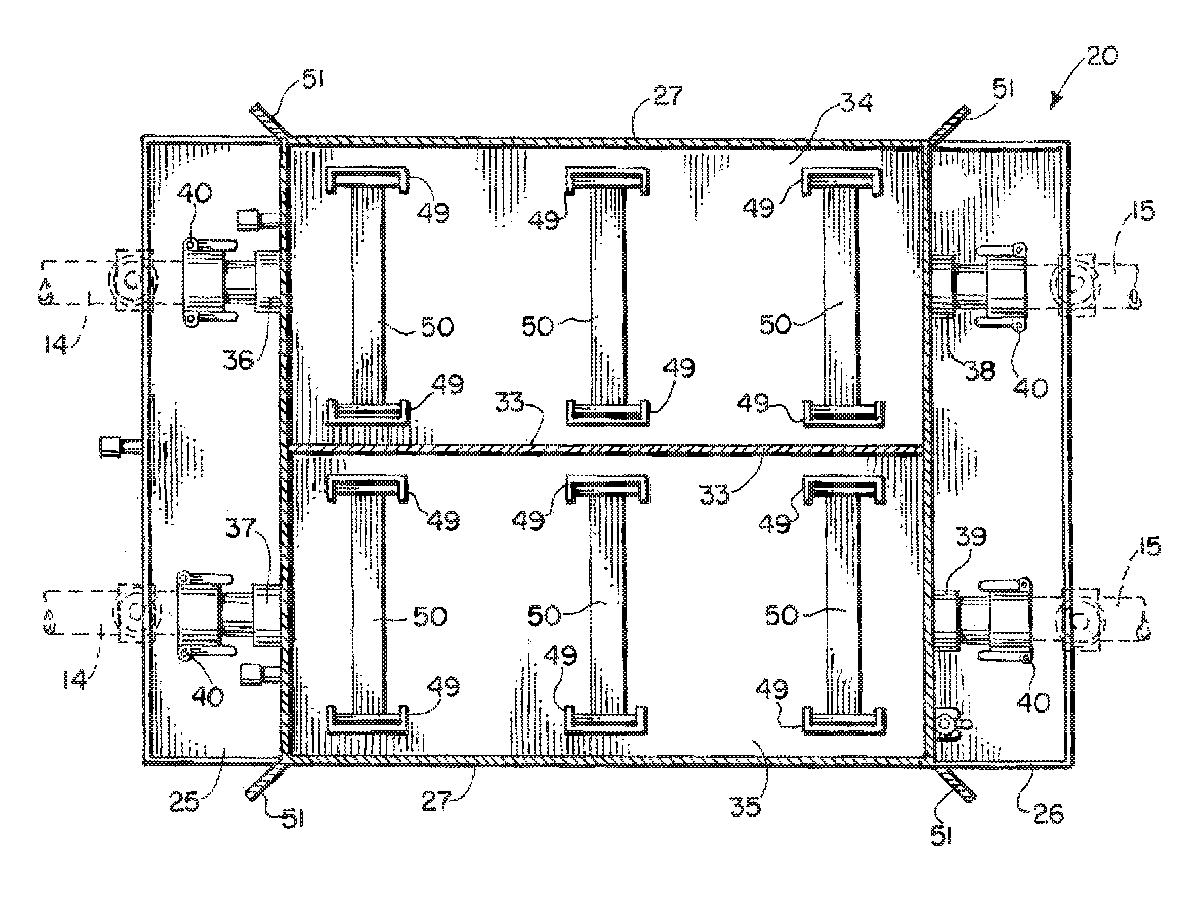
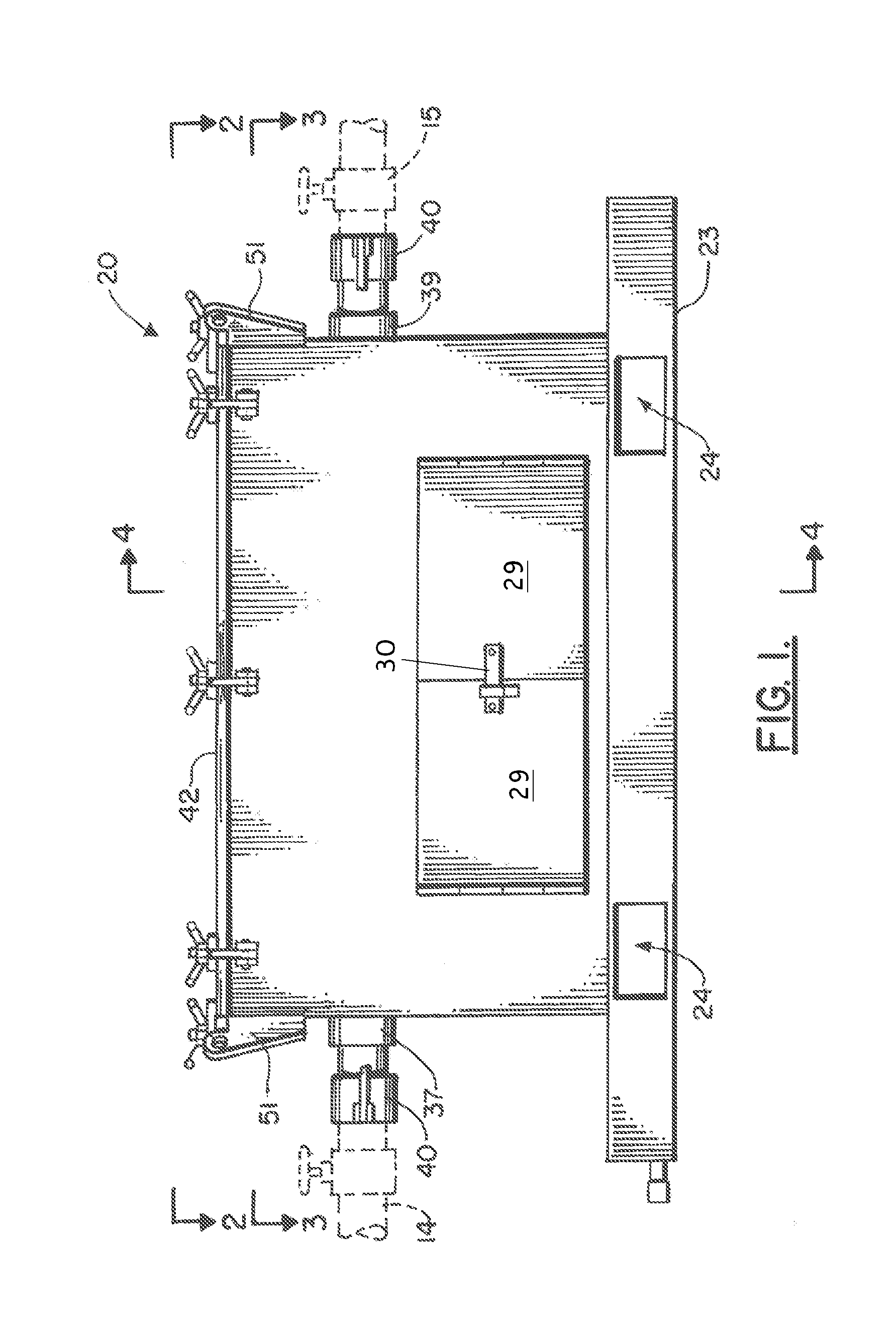
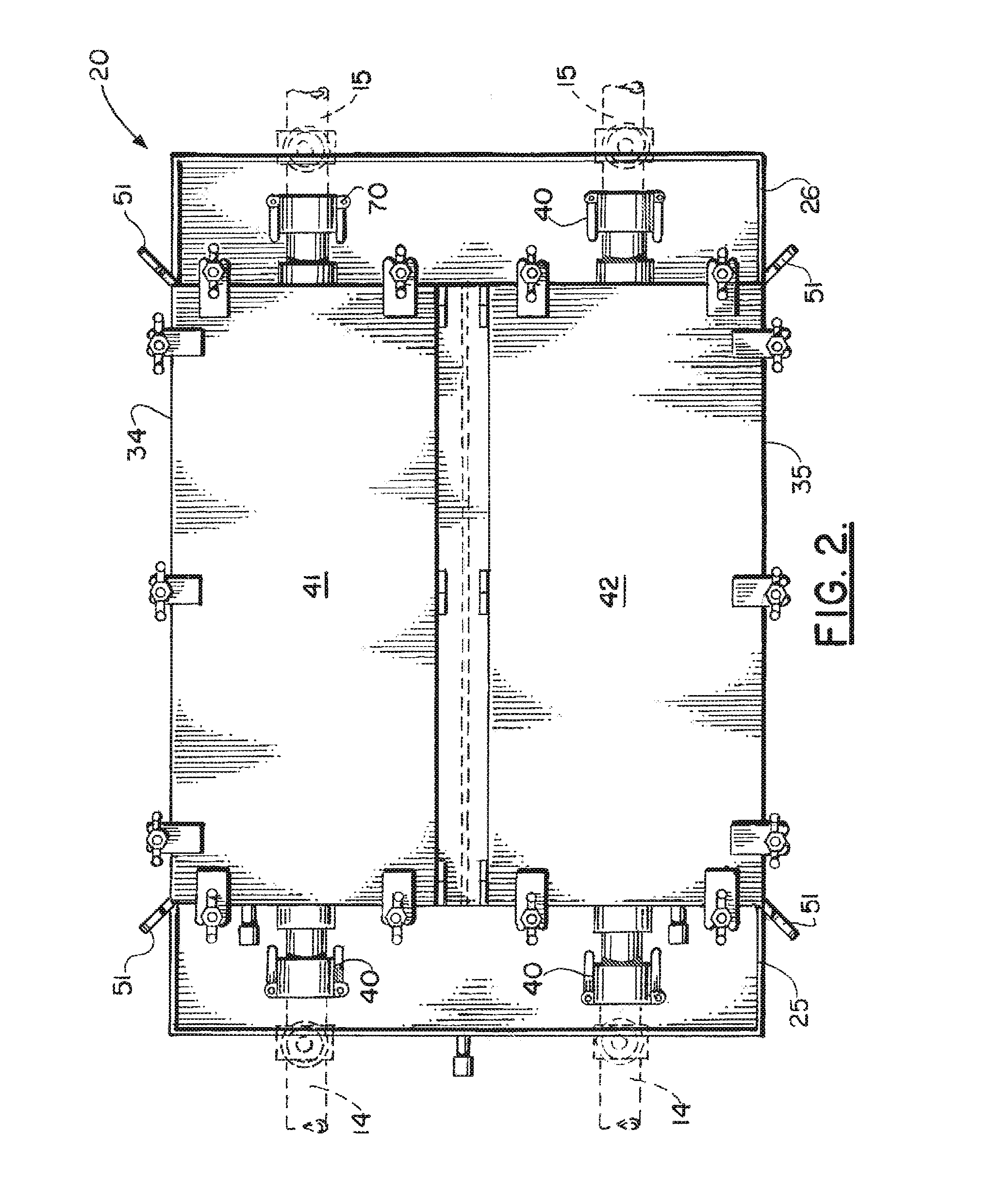
[0039]FIGS. 1-6 show the preferred embodiment of the apparatus of the present invention designated generally by the numeral 10. The system 10 for removing metallic particles from an oil well circulating fluid stream employs a specially configured treatment vessel 20 having a pair of fluid flow sections 34, 35. Each of the sections 34, 35 is equipped with a magnetic field that removes metallic materials as they flow through the section 34 or 35.

[0040]FIG. 6 illustrates the method and apparatus of the present invention, designated generally by the numeral 10. In FIG. 6, the influent flow stream 11 from an oil well can be routed to an initial treatment vessel such as shale shaker 12. Flow stream 11 can be any circulating well fluid, e.g. completion fluid. After exiting shale shaker 12, the fluid enters a holding tank 13. An influent manifold 14 communicates between holding tank 13 and treatment vessel 20. Fluid is transmitted via effluent manifold 15 from treatment vessel 20 to pump 16...


PUM

PropertyMeasurementUnit
time periodaaaaaaaaaa
magnetic fieldaaaaaaaaaa
magnetic fieldsaaaaaaaaaa

Abstract

A method and apparatus for removing metallic material from a circulating well fluid stream provides a treatment vessel that is divided into first and second sections. Each of the sections includes a magnetic field that can be in the form of one or more magnets. In one embodiment, multiple magnets are provided in each of the sections. Manifolds attach to an influent and to an effluent of the treatment vessel. Each manifold enables selective transfer of fluid to either of the selected sections. Similarly, discharge of circulating fluid can be from either of the sections via a discharge manifold. The treatment vessel enables continuous treatment by valving fluid flow so that only one section need be used at a time in order that the other section could be serviced for removing collected metallic material from the magnetic field or from the magnets.

Description

CROSS-REFERENCE TO RELATED APPLICATIONS[0001]Priority of U.S. Provisional Patent Application Ser. No. 61 / 182,406, filed May 29, 2009, incorporated herein by reference, is hereby claimed.STATEMENT REGARDING FEDERALLY SPONSORED RESEARCH OR DEVELOPMENT[0002]Not applicableREFERENCE TO A “MICROFICHE APPENDIX”[0003]Not applicableBACKGROUND OF THE INVENTION[0004]1. Field of the Invention[0005]The present invention relates to a method and apparatus for removing metallic matter (e.g. metal shavings, metal parts, iron, iron oxide and like metallic material from a flow stream of circulating oil well fluid, such as completion fluid.[0006]2. General Background of the Invention[0007]Magnets have been used to remove metal from a flow stream of oil well drilling mud. Examples of commercially available magnets can be seen at the Stacey Oil Services, Ltd. website (www.staceyoil.com) and the Ceesan website (www.ceesan.net). Such magnets are also known in the industry as “ditch magnets”. Some patents h...

Claims


Application Information

Patent Timeline
Patent Type & Authority Applications(United States)
IPC IPC(8): B03C1/30
CPCB03C1/30B03C2201/20B03C2201/18B03C1/02B03C1/0332B03C1/0335B03C1/286B03C2201/28E21B21/065
Inventor WILLIAMSON, PATBOUDREAUX, HOMERCALLEGARI, STEVECALLEGARI, JR., STEVEFOLEY, LARRYFONTENOT, RAPHAEL
Owner GASOLINEEUM SPECIALTY RENTAL
Learn More