Wind turbine generator and method of controlling the wind turbine generator

Inactive Publication Date: 2011-08-04
MITSUBISHI HEAVY IND LTD
View PDF25 Cites 29 Cited by
  • Summary
  • Abstract
  • Description
  • Claims
  • Application Information

AI Technical Summary

Benefits of technology

In this manner, the wind turbine generator of the present invention can easily stop the wind turbine blades at a desired position. Furthermore, because there is no need to suddenly stop the wind turbine blades while generating power, an impact exerted on the wind turbine generator due to a sudden stop can be prevented.

Problems solved by technology

However, it has been difficult to predict the stop position (angle) of the wind turbine when the rotating wind turbine is to be stopped.

Method used


Image

  • Wind turbine generator and method of controlling the wind turbine generator
  • Wind turbine generator and method of controlling the wind turbine generator
  • Wind turbine generator and method of controlling the wind turbine generator

Examples


first embodiment

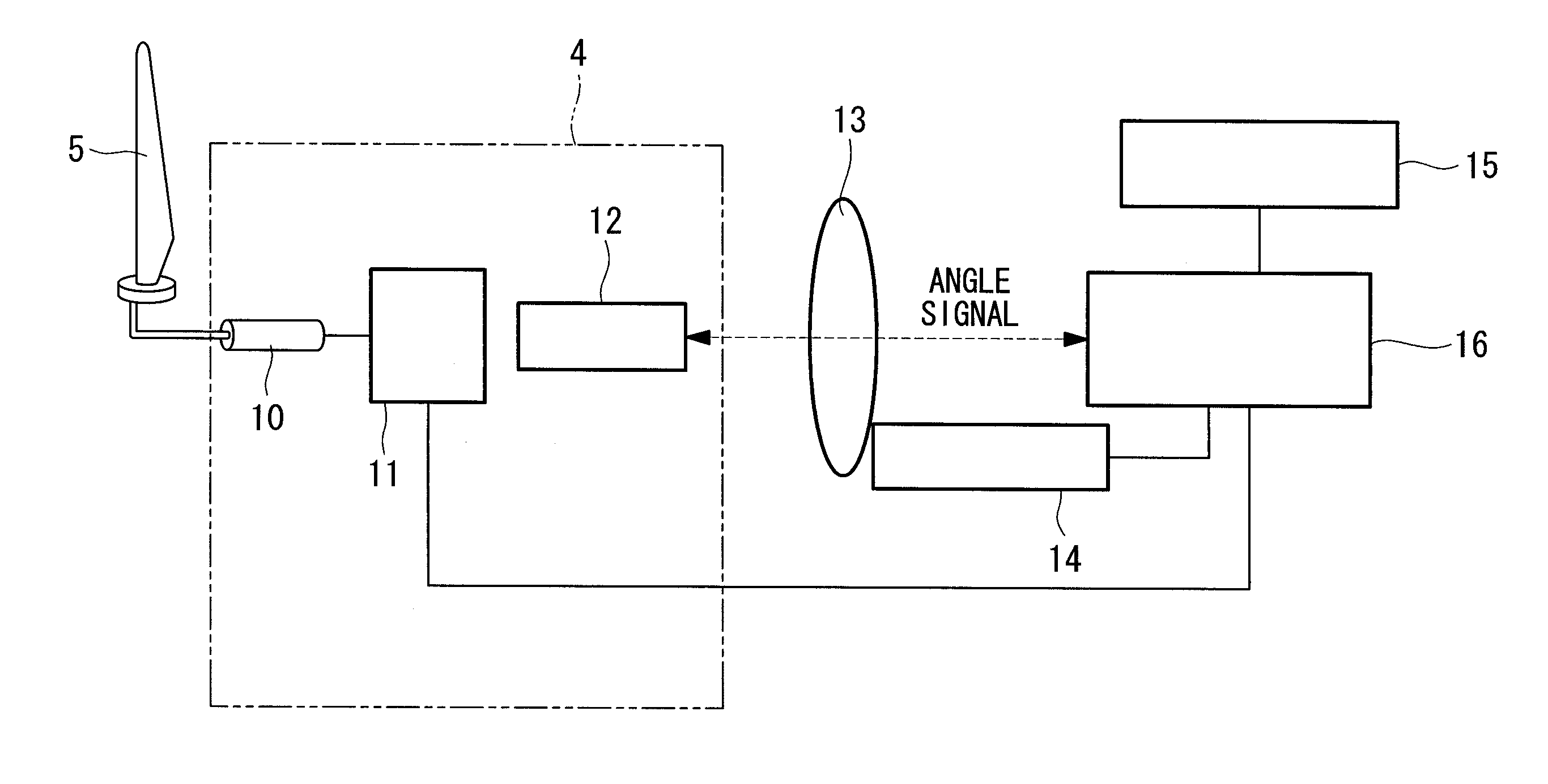
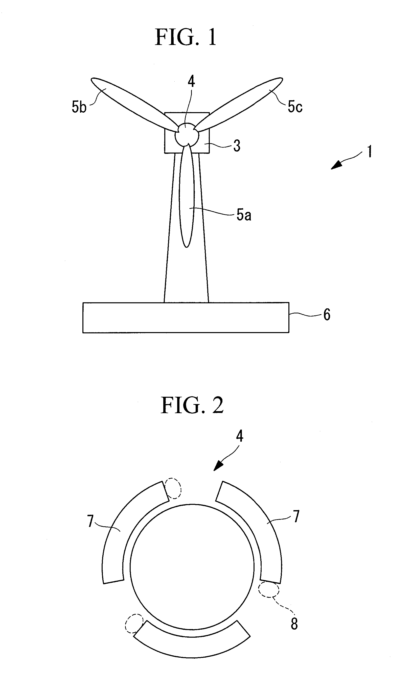
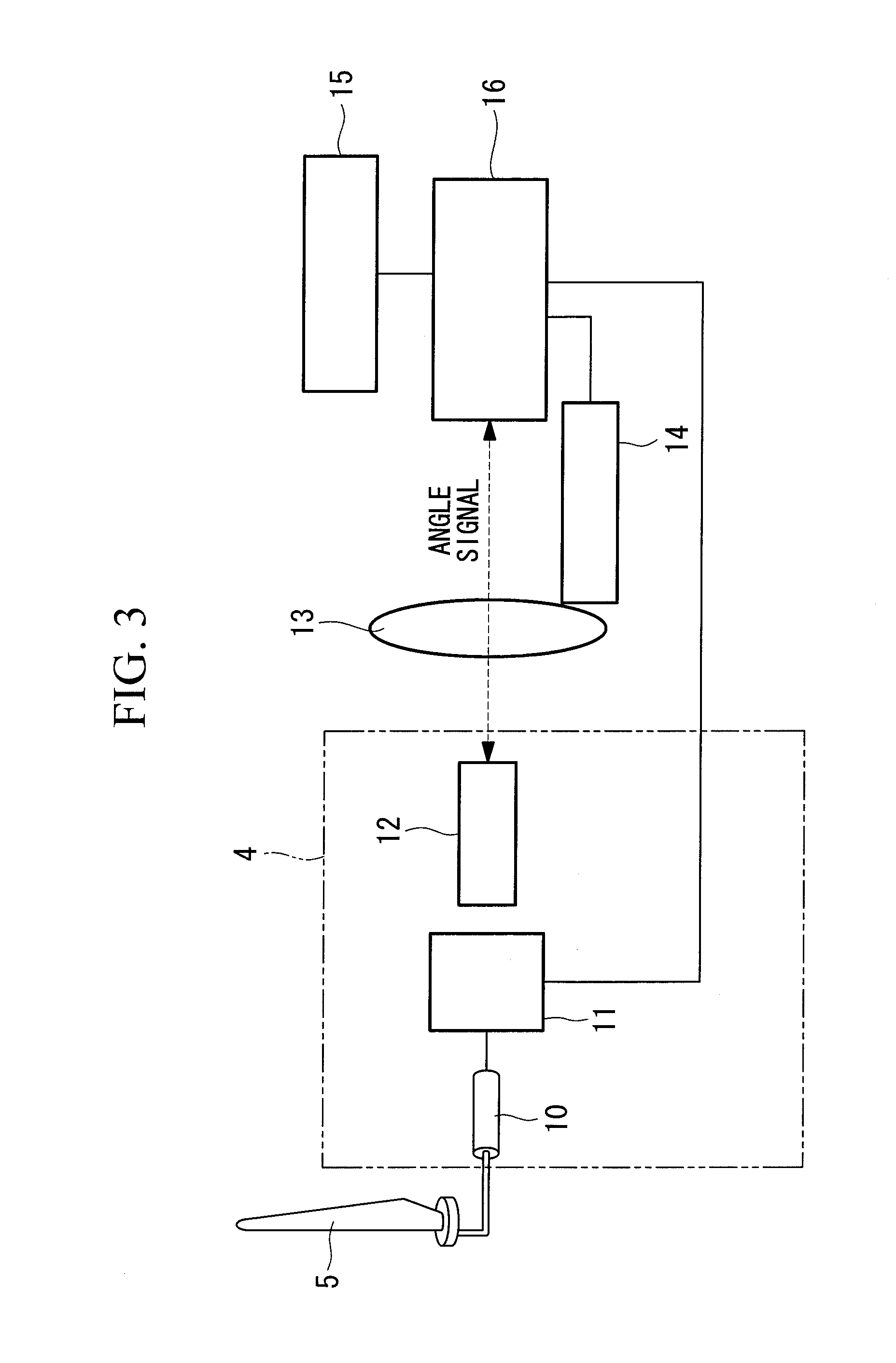
FIG. 1 is a front view showing, in outline, the configuration of a wind turbine generator of the present invention.

As shown in FIG. 1, a wind turbine generator 1 includes a tower 2 installed upright on supporting ground 6, a nacelle 3, a rotor head 4, and three wind turbine blades 5a, 5b, and 5c (hereinafter generally referred to as “wind turbine blades 5” when no specific distinction is needed). The nacelle 3 is provided on top of the tower 2 via a bearing device so as to be capable of turning about the axis of the tower 2. The rotor head 4 is attached to one end of the nacelle 3 via a main shaft (not shown) so as to be rotatable about the horizontal axis of the nacelle 3. As shown in FIG. 2, fences 7 are provided on the back surface of the rotor head 4, at positions where the wind turbine blades 5 are attached, and hatches 8 are provided between the fences 7. During maintenance, an operator can enter or exit through the hatches 8. The wind turbine blades 5 are attached radially ar...

second embodiment

Next, a second embodiment of the present invention will be described using FIGS. 6 and 7. Descriptions of the configurations common to the above-described first embodiment will be omitted, and only descriptions of configurations different therefrom will be given.

This embodiment is different in that a disc 20 connected to the rotor head 4 via the main shaft is provided, instead of the brake disc 13 and the brake device 14 in the first embodiment, and the stop position of the wind turbine blades 5 is controlled by an electromagnet 22 and a magnet 21 attached to the disc 20. That is, the magnet 21 is provided on the disc 20 in advance, at a position corresponding to the position at which the rotor head 4 or the wind turbine blades 5 are to be stopped, and the electromagnet 22 that can be magnetized in such a direction that it attracts the magnet [[20]]21 by a control signal from the stop-position control device 16 is provided. Furthermore, the electromagnet 22 is provided opposite the ...

third embodiment

Next, a third embodiment of the present invention will be described using FIGS. 9 and 10. Descriptions of the configurations common to the above-described first embodiment will be omitted, and only descriptions of configurations different therefrom will be given.

This embodiment is different in that a first gear 30 is provided, instead of the brake disc 13 and the brake device 14 in the first embodiment, and a second gear 31 that is connected to the first gear 30 and can be driven by a motor 32 is provided. That is, the first gear 30 is provided so as to be connected to the rotor head 4 via the main shaft and rotated together with the wind turbine blades 5. The second gear 31 is provided so as to be driven by the small motor 32, so that the rotation of the second gear 31 is transmitted to the first gear 30. The motor 32 is driven and controlled by the stop-position control device 16, and a small output motor that can rotate the wind turbine blades 5 at low speed, e.g., a predetermine...


PUM


Abstract

A wind turbine generator capable of easily stopping wind turbine blades at an appropriate position in a short time is provided. A pitch control device controls the pitch angle to a feather side to reduce the rotational speed of the wind turbine blades to a predetermined speed upon receiving a stop signal instructing stopping the rotation of the wind turbine blades, and, on the basis of a detection result of an angle detection device, a brake disc and a brake device are driven and controlled so that the rotation of the wind turbine blades is stopped at a desired position.

Description

TECHNICAL FIELDThe present invention relates to wind turbine generators that generate power using wind turbines for converting wind, which is a natural energy, into a rotational force, and, more specifically, it relates to wind turbine generators that include a stop-position control device for stopping the wind turbine at a desired position.BACKGROUND ARTConventionally, wind turbine generators that generate power using wind force, which is a natural energy, are known. The wind turbine generators of this type have a rotor head, which includes a nacelle mounted on a tower and wind turbine blades attached thereto, a main shaft connected so as to rotate together with this rotor head, a gearbox to which the main shaft rotated by receiving wind force with the wind turbine blades is connected, and a generator driven by the shaft output power from the gearbox. In the wind turbine generators having such a configuration, the rotor head having the wind turbine blades that convert wind force in...

Claims


Application Information

Patent Timeline
IPC IPC(8): H02P9/04
CPCF03D7/0244Y02E10/723F05B2270/328F03D7/0248F03D7/0268Y02E10/72F03D7/04
Inventor TOYOHARA, TAKASHIHASHIMOTO, MASAYUKIMATSUSHITA, TAKATOSHI
Owner MITSUBISHI HEAVY IND LTD
Why Eureka
Try Eureka