
Method and System for Data Center Rack Brackets For Automatic Location Tracking of Information Technology Components

Inactive Publication Date: 2011-08-04
AVOCENT CORP
View PDF48 Cites 31 Cited by
  • Summary
  • Abstract
  • Description
  • Claims
  • Application Information

AI Technical Summary

Benefits of technology

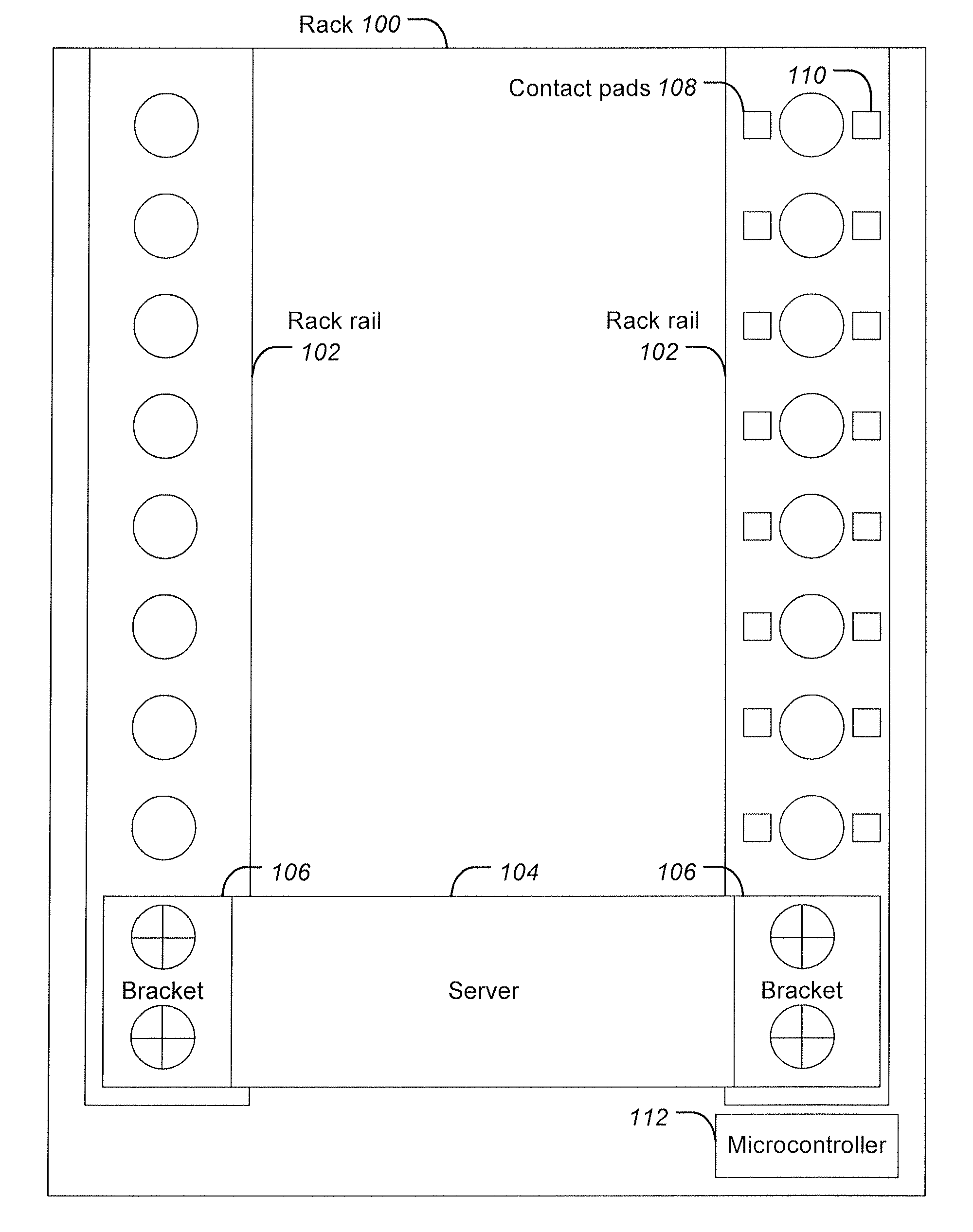
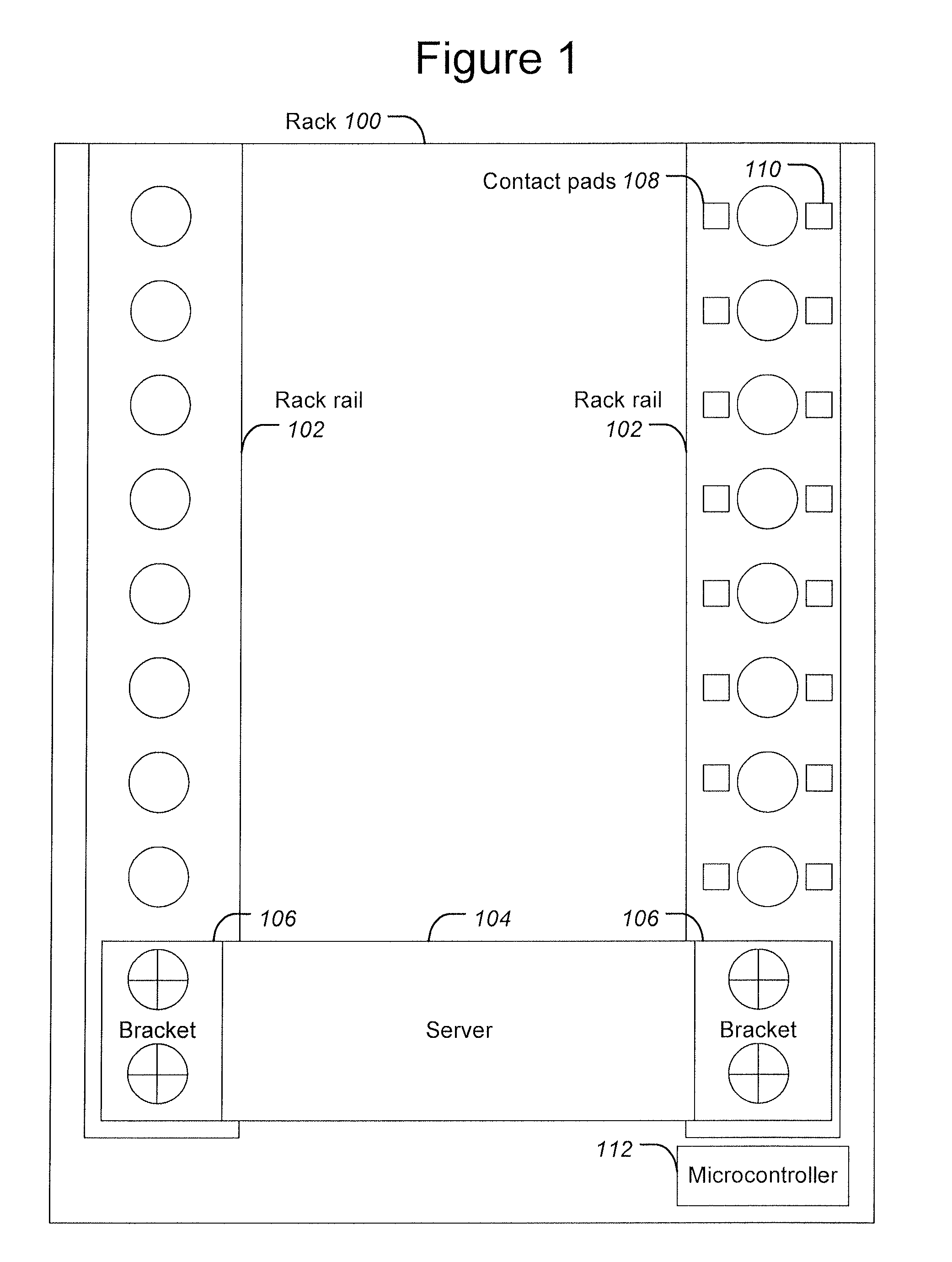
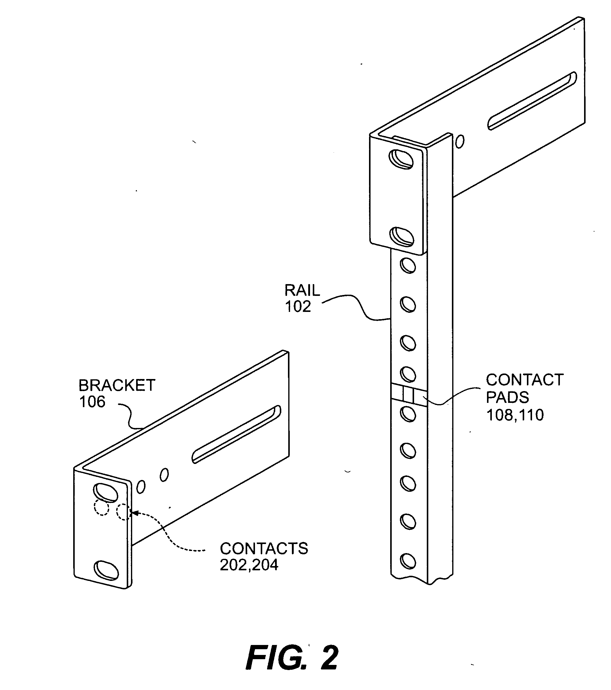
In accordance with methods and systems consistent with the present invention, a method is provided in a data processing system for automatically tracking locations of IT components in a data center, comprising attaching a bracket comprising an ID chip uniquely identifying the bracket to an IT component, and associating the bracket with the attached IT component. The method further comprises inserting the IT component into a slot in a rack, the slot comprising one or more contacts configured to connect to the ID chip on the bracket, automatically determining a presence of the bracket in the rack based on the ID chip, and automatically determining a position of the bracket in the slot in the rack.
In accordance with an implementation, a data processing system is provided for automatically tracking locations of IT components in a data center, comprising a bracket configured to attach to an IT component and comprising an ID chip uniquely identifying the IT component. The data processing system further comprises a rack comprising one or more slots, the slots configured to store an IT component and comprising one or more contacts configured to connect to the ID chip on the bracket. Furthermore, the data processing system comprises a microcontroller configured to determine a presence of the bracket and a position

Problems solved by technology

In these cases, if the database for tracking the location of these components is not updated, conventionally a manual process, the database will be outdated and contain inaccurate information.
A technician's reliance on this incorrect information can be greatly detrimental.
Many organizations use enterprise asset management solutions to help manage their valuable IT assets, but find that updating asset information, such as their physical location, still requires extensive manual effort.
If an IT component is not properly accounted for, it is no longer visible, and increases the risk of underutilization of the component, or it being lost or stolen.
Manual audits are an expensive and time-consuming process, and manually managing these assets significantly adds to IT costs.
These systems do not give the users an automatic, instantaneous and cost effective way of knowing where a given IT component is located at any point in time within the data center.
They do not provide a way for users to automatically have up-to-date physical location information for where an IT component is within a given data center room, on which rack they it resides, or in which slot within a rack.
These processes are often violated through human error, leaving the database with incorrect information.
As a result, conventional systems do not allow users to be sure that when remotely managing location information of a given server or device the right server or device will be managed.
Some conventional RFID systems do not provide a cost-effective way of identifying IT components down to the slot-level in a rack.

Method used


Image

  • Method and System for Data Center Rack Brackets For Automatic Location Tracking of Information Technology Components
  • Method and System for Data Center Rack Brackets For Automatic Location Tracking of Information Technology Components
  • Method and System for Data Center Rack Brackets For Automatic Location Tracking of Information Technology Components

Examples


Embodiment Construction

Methods and systems in accordance with the present invention provide the automatic tracking and management of the physical location of information technology components in a data center. These methods and systems automatically identify where a given IT component, such as a server, router, switch or other device, is located. In particular, they automatically identify which slot the IT component is located in a given rack in the data center. When a server, for example, is added or removed from a particular slot, the tracking database is automatically notified and updated, and users of the database have instantaneously accurate information about the location of each IT component in a data center. If the server is changed to a different slot or rack, the system immediately identifies that the given server or device is located in a different location. Users can confidently rely on the information in the database when remotely managing the data center's IT assets. These systems allow user...


PUM


Abstract

Methods and systems provide the automatic tracking of the physical location of information technology components in a data center. These systems automatically identify where a given IT component, such as a server, router, switch or other device, is located. They automatically identify which slot the IT component is located in a given rack in the data center. They include “smart” brackets containing small ID chips attached to the rack-based IT components and a “smart” rack rail for detecting the brackets. Each smart bracket uniquely identifies the IT component to which it is attached. The smart rack rail identifies the slot of the rack in which the IT component resides and communicates with a microcontroller to relay the position information to a database.

Description

FIELD OF THE INVENTIONThis generally relates to information technology components in a data center, and more particularly to automatic location tracking of information technology components, such as servers, routers and switches, in a data center.BACKGROUNDData centers are buildings or rooms that house large numbers of information technology components such as computing equipment (e.g., servers, data processors, appliances), storage networking equipment (e.g., switches, routers, patch panels) and power equipment (e.g., UPS, power strips) or other computer components. Typically, the interior of a data center is filled with multiple rows of cabinet-like equipment called racks that are arranged in parallel to one another throughout the data center. Each rack houses multiple, vertically spaced components, and an aisle for service personnel is often provided between rows of racks. In this way, a large number of servers or other components can be placed in a data center. Alternatively, th...

Claims


Application Information

Patent Timeline
IPC IPC(8): G08B5/22G06F17/30
CPCH05K7/1498
Inventor COSTA, MARIOGEFFIN, STEVEN
Owner AVOCENT CORP
Learn More