
Method for a server-less office architecture

a server-less office and server technology, applied in the field of server-less office architecture, can solve the problems of departmental fiefdoms, limited user access and tightly controlled, and often emerged departmental fiefdoms, so as to achieve efficiency, gain efficiency, and effectiveness.

Inactive Publication Date: 2005-12-29
EPLUS CAPITAL
View PDF15 Cites 181 Cited by
  • Summary
  • Abstract
  • Description
  • Claims
  • Application Information

AI Technical Summary

Benefits of technology

[0016] improved security from virtual private networks (VPNs), Firewalls, DMZs where DMZ=demilitarized zone, a computer or small sub network that sits between a trusted internal network such as a corporate private local area network (LAN), and an untrusted external network, such as the public Internet;
[0103] User Interface—Today's technologies offer several alternatives for user's connection devices. In a preferred embodiment, the server-less office reduces costs and administrative overhead by utilizing thin clients. It is no longer necessary to provide high-power PC's, workstations or laptops for mainstream business applications on the network. Thin clients or terminals provide all the connectivity necessary and reduce costs. Thin clients deployed properly can also enhance security schemes by allowing access only to prescribed resources and preventing users from installing unauthorized applications.

Problems solved by technology

Twenty-fine years ago the Information Technology (IT) industry could be characterized as follows; there was no personal computing; mainframes were king; processing and storage were expensive; software was developed in-house or available from a few vendors; and user access was limited and tightly controlled.
And, as a result, departmental fiefdoms often have emerged, characterized by counterproductive political and budgetary infighting to gain the leverage to implement independent architectures to meet individualized group needs without first considering the overall needs of the organization.

Method used


Image

  • Method for a server-less office architecture
  • Method for a server-less office architecture
  • Method for a server-less office architecture

Examples


Embodiment Construction

[0114] It is to be understood by persons of ordinary skill in the art that the following descriptions are provided for purposes of illustration and not for limitation. An artisan understands that there are many variations that lie within the spirit of the invention and the scope of the appended claims. Unnecessary detail of known functions and operations may be omitted from the current description so as not to obscure the present invention.

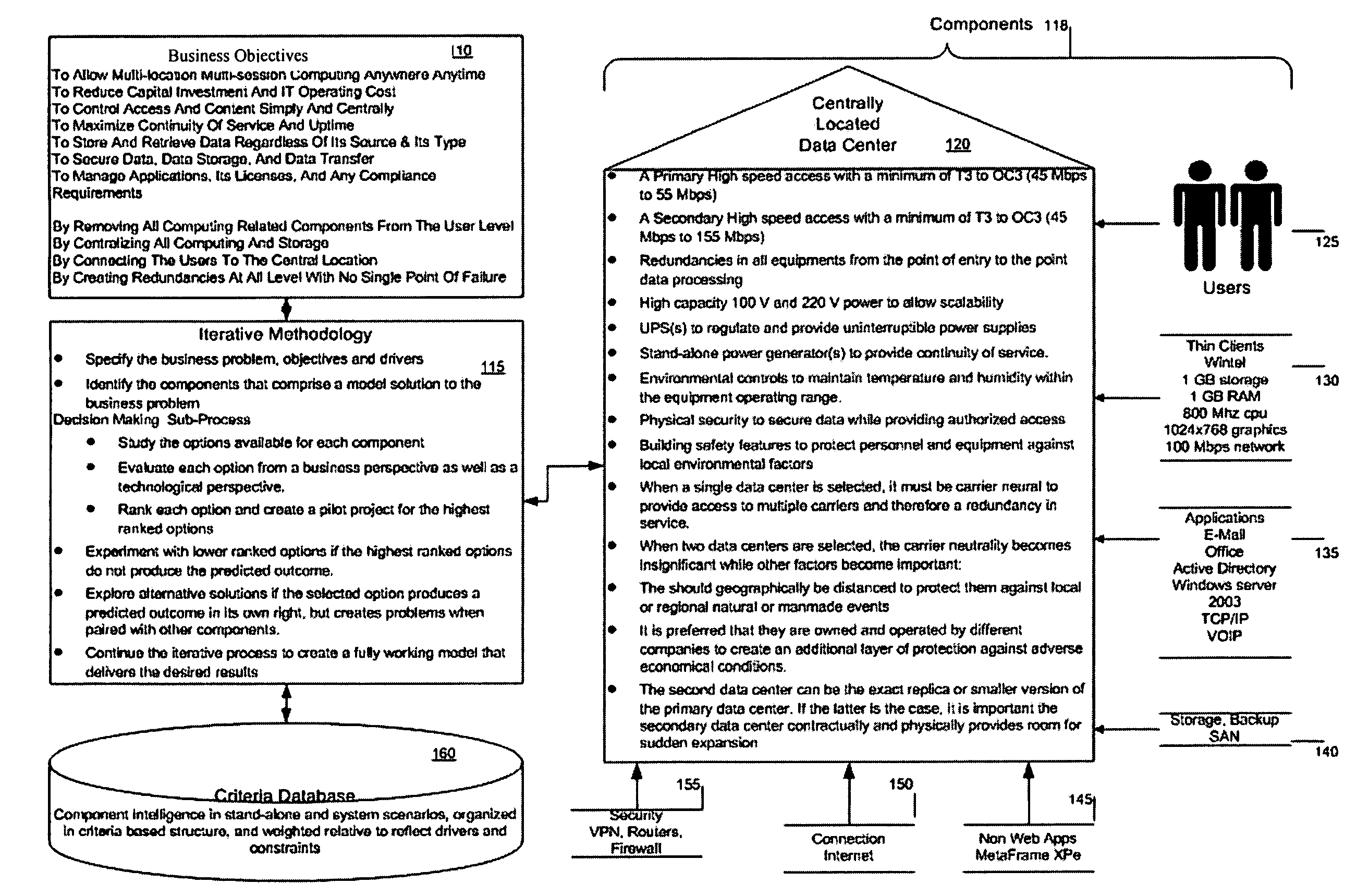
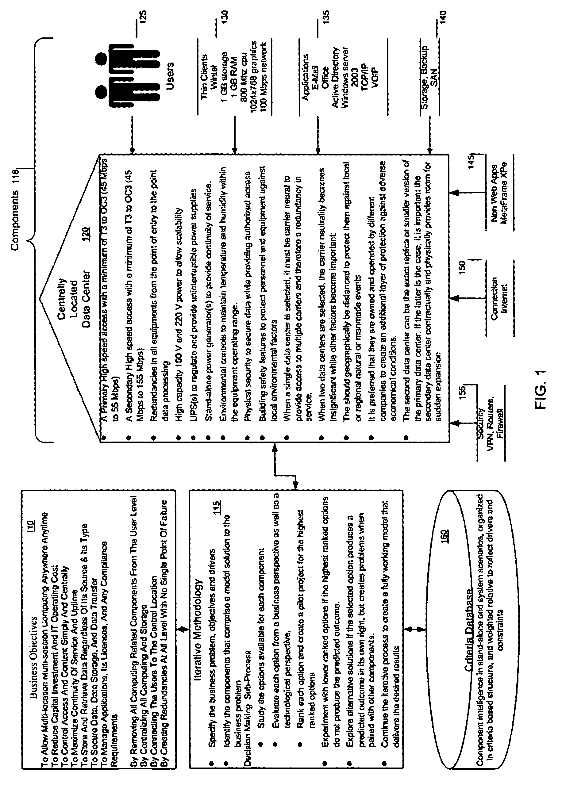
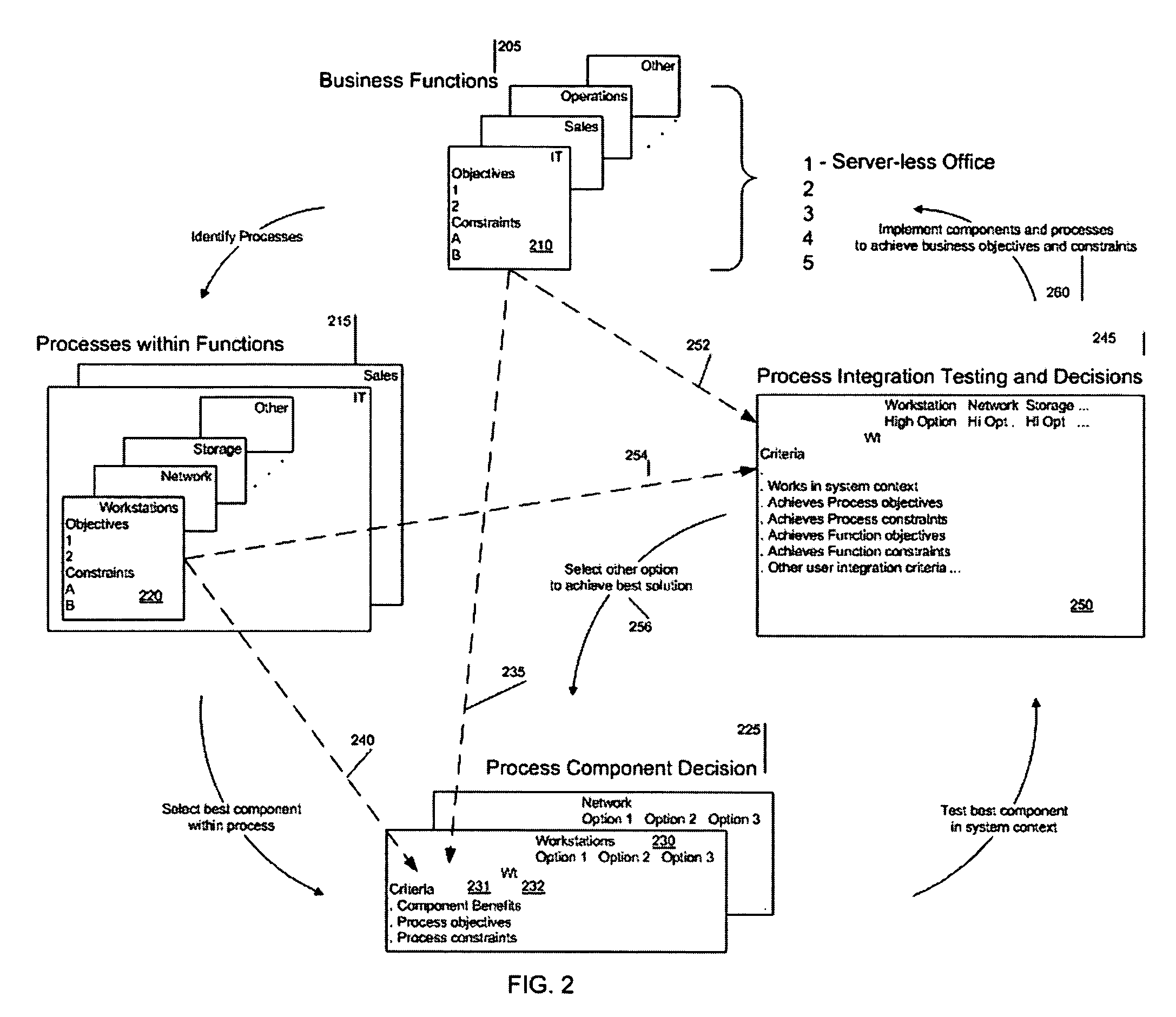
[0115] In the following disclosure an example of the framework-guided method of the preferred embodiment is provided as applied to a hypothetical set of business objectives and business constraints. A set of candidate IT components is selected to meet these objectives and satisfy these constraints. Then, a preferred embodiment of the present invention is applied to derive an architecture based on the set of candidate IT components that ‘best’ meets the business objectives and business constraints.

[0116]FIG. 1 illustrates the interrelationship be...


PUM


Abstract

A way is provided for architecting a server-less office that delivers anywhere anytime computing support to an organization. The server-less office comprises a plurality of information technology IT components selected based on business objectives and constraints associated with the business function of the organization to work together to deliver computing support functions to a plurality of end users who no longer have local computing support and may only have thin clients on their desks. A pre-determined server-less architecture is imposed by the present invention by including at least four architectural groupings of IT components that the organization must map the objectives and constraints of its business functions onto for IT component selection purposes. A local group is included in this minimum set of groups so that unique processing needs can be satisfied that are not met by the imposed pre-determined server-less office architectural groupings.

Description

REFERENCE TO RELATED APPLICATION [0001] This application claims the benefit of U.S. provisional application Ser. No. 60 / 582,802, filed Jun. 28, 2004, the entire disclosure of which is herein incorporated by referenceBACKGROUND OF THE INVENTION [0002] 1. Field of the Invention [0003] The present invention relates to a method for defining a server-less office architecture that meets pre-determined business objectives and business constraints by providing users thereof anywhere anytime access to appropriate IT resources. [0004] 2. Description of the Related Art [0005] Twenty-fine years ago the Information Technology (IT) industry could be characterized as follows; there was no personal computing; mainframes were king; processing and storage were expensive; software was developed in-house or available from a few vendors; and user access was limited and tightly controlled. [0006] Five years ago the landscape was changing: personal computers were ubiquitous and a common organizational goa...

Claims


Application Information

Patent Timeline
IPC IPC(8): G06F21/00G06F21/33G06F21/34G06F21/41G06Q10/00
CPCG06Q10/00G06Q30/02G06Q10/10
Inventor TABRIZI, MAJID
Owner EPLUS CAPITAL
Learn More