
Method and system for estimating position using dual real time kinematic engines

a technology of real-time kinematics and estimation methods, applied in the field of methods, can solve the problems of error-reducing filter approaches, and the raim technique cannot be fully addressed

Active Publication Date: 2011-08-04
DEERE & CO
View PDF6 Cites 20 Cited by
  • Summary
  • Abstract
  • Description
  • Claims
  • Application Information

AI Technical Summary

Benefits of technology

[0005]In accordance with one embodiment, the method and system for estimating the position of an object or a vehicle comprises measuring a first carrier phase of a first carrier signal and a second carrier phase of a second carrier signal received by a location-determining receiver. A primary real time kinematic (RTK) engine or a receiver data processing system estimates a primary integer ambiguity set associated with at least one of the measured first carrier phase and the measured second carrier phase. A quality evaluator determines if a primary integer ambiguity set is resolved correctly to the predefined reliability rate during an earlier evaluation period (e.g., an epoch). A secondary real time kinematic (RTK) engine or receiver data processing system estimates a secondary integer ambiguity set associated with at least one of the measured first carrier phase and the measured second carrier phase during a later period (e.g., a later epoch) following the earlier evaluation period.

Problems solved by technology

Neither the error-reducing filter approach, nor the RAIM technique fully addresses the aforementioned problem of imprecise pseudo-range and carrier phase measurements, where the location-determining receiver receives (e.g., transiently) one or more satellite signals of low signal strength or poor signal quality.

Method used


Image

  • Method and system for estimating position using dual real time kinematic engines
  • Method and system for estimating position using dual real time kinematic engines
  • Method and system for estimating position using dual real time kinematic engines

Examples


Embodiment Construction

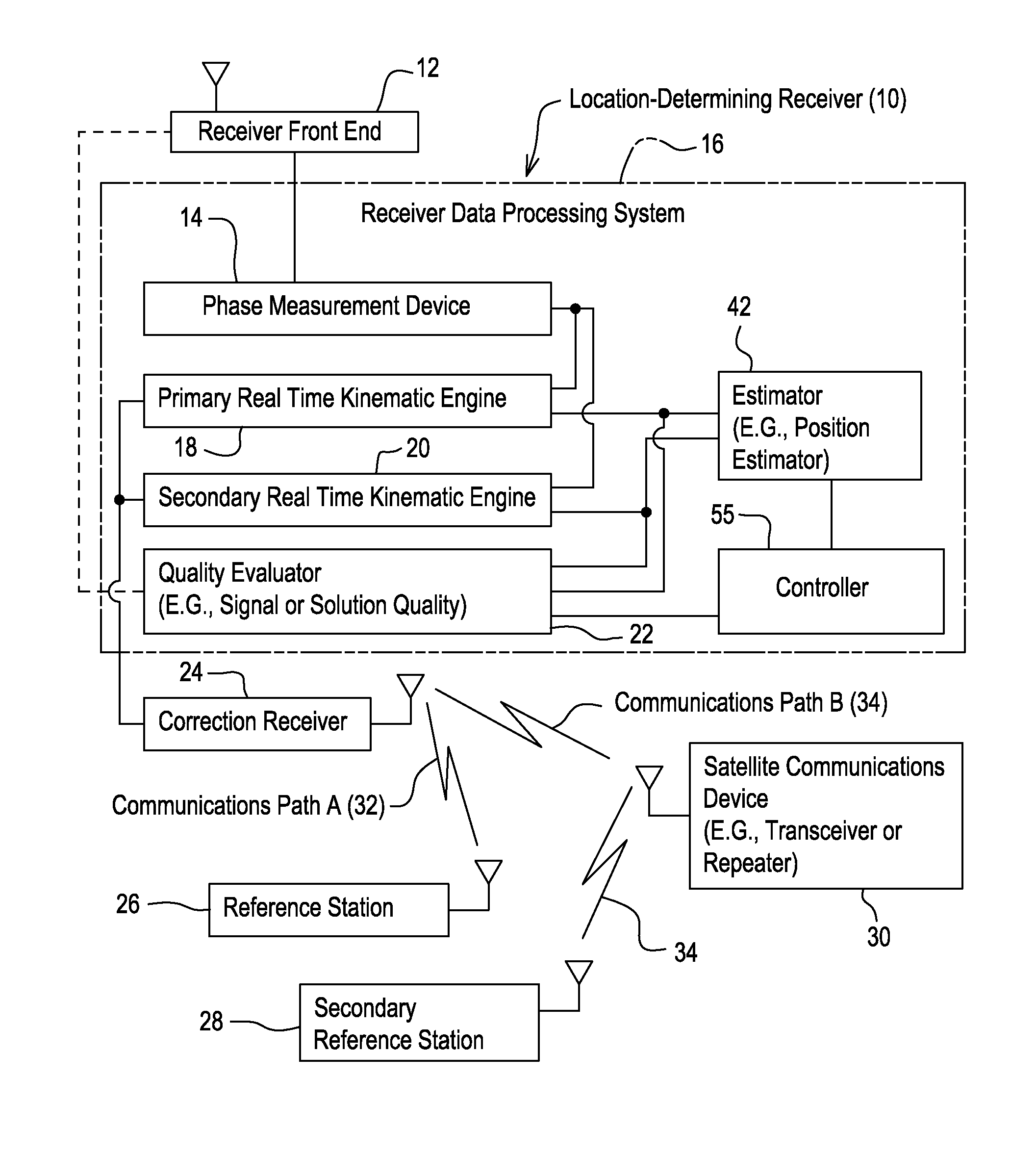
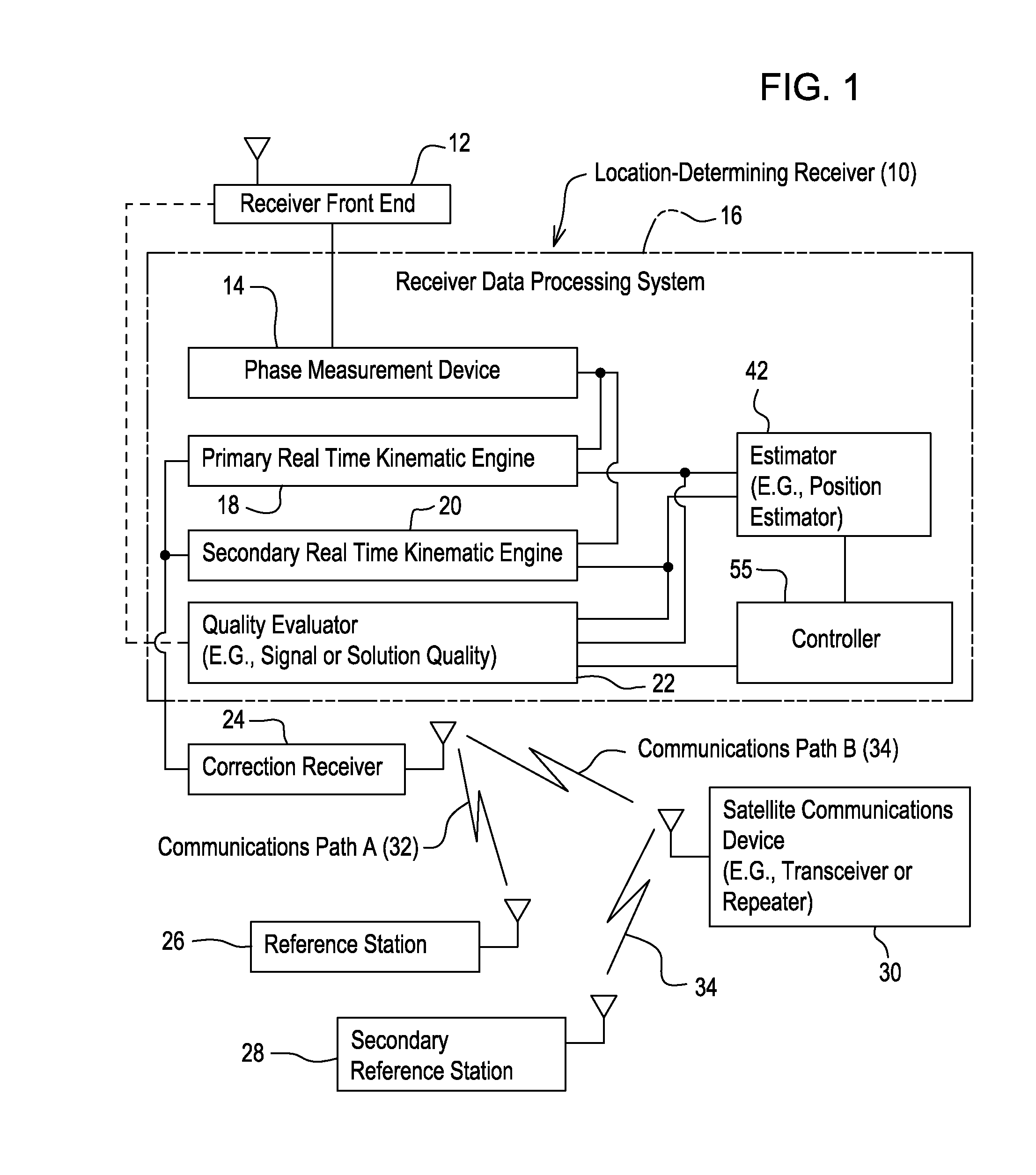
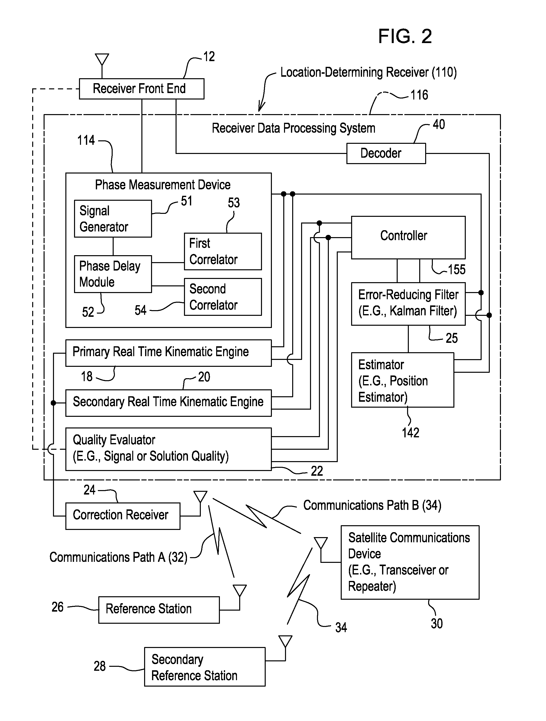
[0015]FIG. 1 illustrates a location-determining receiver 10 that comprises a receiver front end 12 coupled to a receiver data processing system 16. The location-determining receiver 10 is associated with a correction receiver 24. The correction receiver 24 may be integrated into the location-determining receiver 10 or may communicate with the location-determining receiver 10 via a data port. The correction receiver 24 receives correction data (e.g., reference carrier phase correction data) from at least one of a reference station 26 and a secondary reference station 28. The reference station 26 communicates via a wireless or electromagnetic signal to the correction receiver 24 via communications path A (32), for example. The secondary reference station 28 communications via wireless or electromagnetic signals to the correction receiver 24 via a satellite communications device 30 via communications path B (34), for example.

[0016]The receiver data processing system 16 may comprise any...


PUM


Abstract

A method and system for estimating the position comprises measuring a first carrier phase of a first carrier signal and a second carrier phase of a second carrier signal received by a location-determining receiver. A primary real time kinematic (RTK) engine or receiver data processing system estimates a primary integer ambiguity set associated with at least one of the measured first carrier phase and the measured second carrier phase. A quality evaluator determines if a primary integer ambiguity set is resolved correctly to the predefined reliability rate during an earlier evaluation period. A secondary real time kinematic (RTK) engine or receiver data processing system estimates a secondary integer ambiguity set associated with at least one of the measured first carrier phase and the measured second carrier phase during a later period following the earlier evaluation period.

Description

CROSS REFERENCE TO RELATED-APPLICATION[0001]This document claims priority based on U.S. provisional application No. 61 / 299,792, filed on Jan. 29, 2010, and entitled METHOD AND SYSTEM FOR ESTIMATING POSITION USING DUAL REAL TIME KINEMATIC ENGINES, under 35U.S.C. 119(e).FIELD OF THE INVENTION[0002]This invention relates to a method and system for estimating position, attitude, or both of an object or vehicle using dual real time kinematic engines.BACKGROUND OF THE INVENTION[0003]A location-determining receiver, such as a Global Positioning System (GPS) receiver estimates the position, attitude (e.g., tilt, roll, or yaw), or both of an object or a vehicle. The location-determining receiver may experience imprecise pseudo-range and carrier phase measurements, where the location-determining receiver receives (e.g., transiently) one or more satellite signals of low signal strength or poor signal quality.[0004]Certain location-determining receivers may use an error-reducing filter (e.g., K...

Claims


Application Information

Patent Timeline
Patent Type & Authority Applications(United States)
IPC IPC(8): G01S3/02
CPCG01S19/44G01S19/23
Inventor DAI, LIWENWANG, CHAOCHAOESLINGER, DANIEL J.
Owner DEERE & CO
Learn More