
Touch input method and device thereof

Inactive Publication Date: 2011-08-04
ACER INC
View PDF19 Cites 18 Cited by
  • Summary
  • Abstract
  • Description
  • Claims
  • Application Information

AI Technical Summary

Benefits of technology

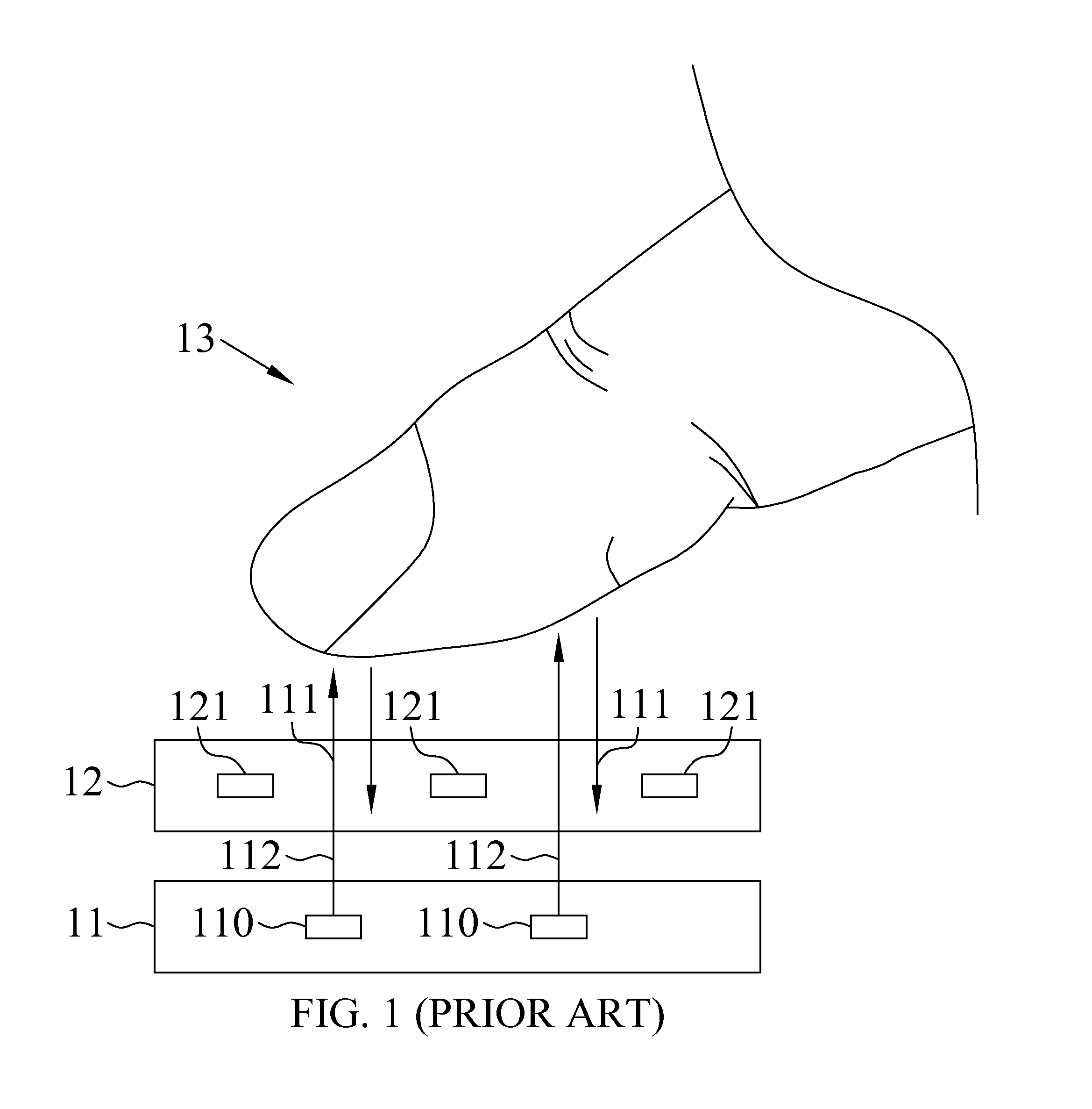
[0005]It is therefore a primary object of the present invention to provide a touch input method and device, so as to solve the problem of failing to have increased image resolution or having reduced object recognition power due to different levels of brightness or colors at different zones of an image displayed on a display screen.
[0011]With the above arrangements, the touch input method and the device thereof according to the present invention has one or more of the following advantages:
[0012](1) With the touch input method and device of the present invention, an image displayed on a display screen is analyzed, and an intensity of an invisible light emitted from the touch display screen is regulated according to a result from the image analysis, so as to obtain increased image resolution.

Problems solved by technology

While the out-cell touch screen can be advantageously applied to a large-size touch display, the touch display adopting the out-cell design must have a predetermined mechanism thickness and therefore fails to be low-profile and light because the touch display must be provided with reflective strips.
However, when the image displayed on the display 12 includes different colors and different levels of brightness, pixels 121 in the display 12 at different positions would show different states, and the reflected lights 112 reflected by the touch object 13 would have different light intensities from one another, which results in reduced resolution in a proximal touch image analysis or easily results in incorrect determination of the object touch position.

Method used


Image

  • Touch input method and device thereof
  • Touch input method and device thereof
  • Touch input method and device thereof

Examples


first embodiment

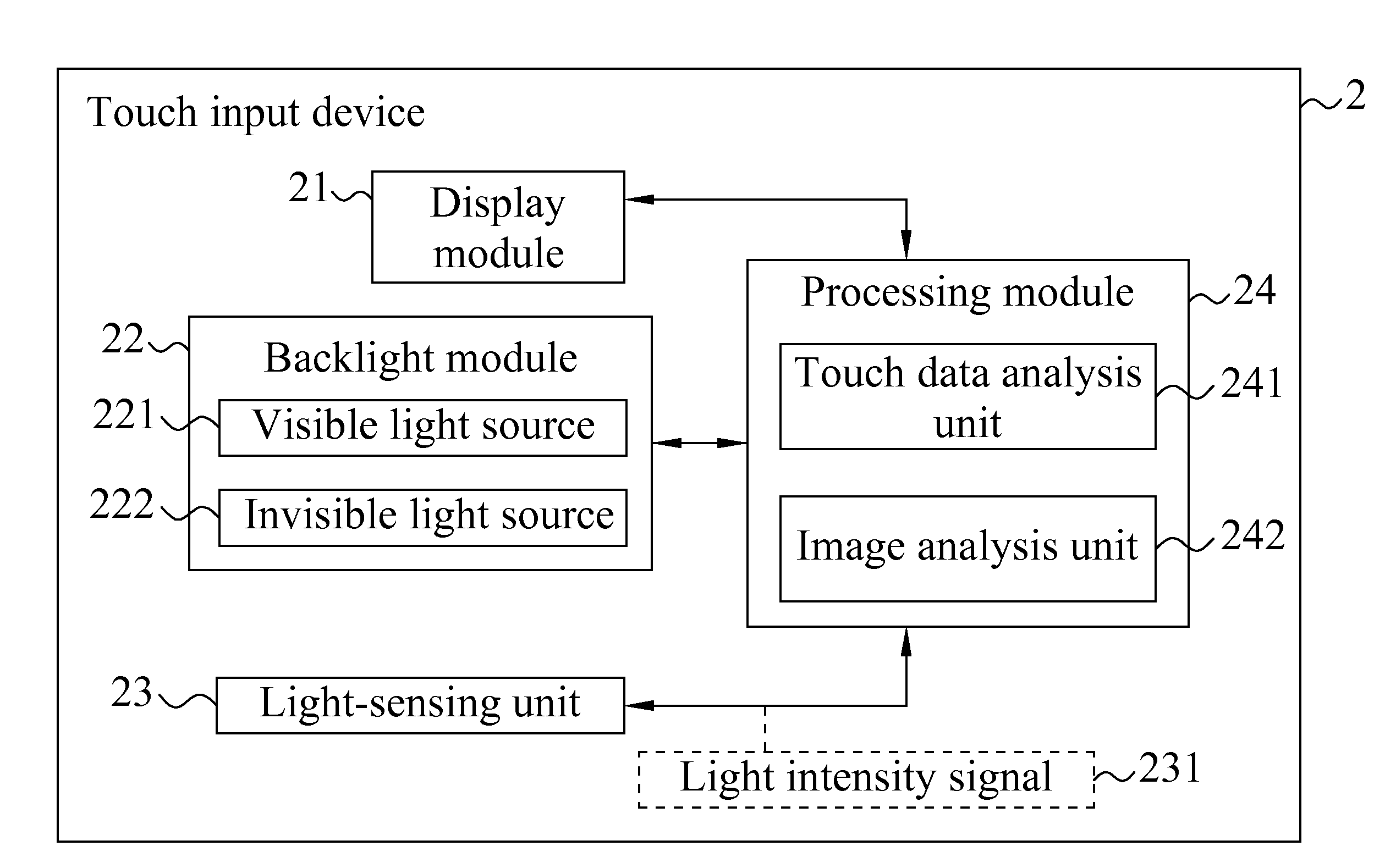
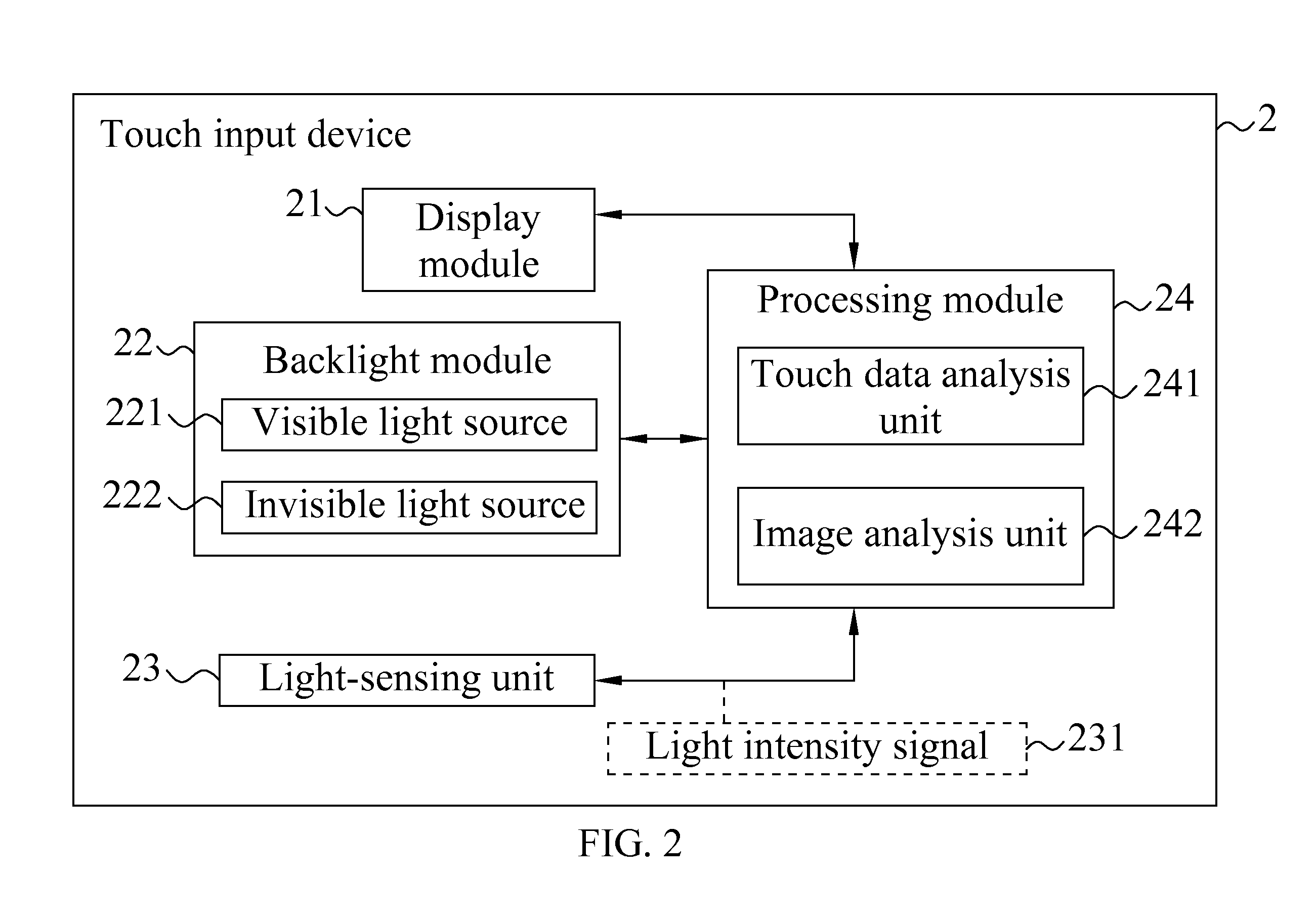
[0029]Please also refer to FIG. 3 that is a schematic cross-sectional view of the display module 21 and the backlight module 22 for the touch input device 2 according to the present invention. In FIG. 3, the display module 21 includes at least one filter unit 211 and at least one light-sensing unit 23. The filter unit 211 is able to absorb a visible light while the light-sensing unit 23 is able to receive an IR light. When an object 26 is in the proximity of a touch surface of the display module 21, an IR light 2221 emitted from the invisible light source 222 of the backlight module 22 would be reflected by the object 26. The light-sensing unit 23 receives the reflected invisible light 2222 and generates a light intensity signal 231 according to the reflected IR light 2222. The light intensity signal 231 is sent to the processing module 24. It is understood the light-sensing unit 23 can be arranged on the touch input device 2 at different positions without being limited to that show...

second embodiment

[0047]In a first step S50 of the touch input method as shown in FIG. 10, use the processing module to receive the light intensity signal.

[0048]In a second step S60, use the processing module to analyze according to the light intensity signal, so as to obtain information about the touch point.

[0049]In a third step S70, use the processing module to adjust the threshold value according to an image analysis result.

[0050]In a fourth step S80, the processing module receives the light intensity signal for a second time and outputs a touch result according to the light intensity signal received the second time.

[0051]Since the steps for producing the image analysis result according to the second embodiment of the touch input method are similar to those included in the flowchart shown in FIG. 7, they are not repeatedly described herein.

[0052]In the first embodiment of the touch input method, the processing module regulates the intensity of the invisible light according to the image analysis ...


PUM


Abstract

A touch input method and a device thereof are disclosed. The touch input device includes a display module for displaying an image, a backlight module for emitting a light source, at least one light-sensing unit for sensing a reflected light of the light source reflected by at least one object on the display module and generating a light intensity signal correspondingly, and a processing module for receiving the light intensity signal and determining based on the light intensity signal at least one touch point on the display module touched by the object. The touch input method is applicable to the touch input device and includes the steps of using the processing module to receive the image, using the processing module to analyze the image and obtain an image analysis result, and regulating a light intensity of an invisible light emitted from the backlight module based on the image analysis result.

Description

FIELD OF THE INVENTION[0001]The present invention relates to a touch input method and a device thereof, and more particularly to a touch input method and a device thereof in which a displayed image content is used as a reference for determining touch information.BACKGROUND OF THE INVENTION[0002]Generally, in a liquid crystal display (LCD), a backlight module is used to produce a light source, and the transmittance of the backlight is changed by controlling the twist and deformation of the liquid crystal, in order to determine the brightness of the image displayed on the display. Currently, the LCD displays the image mainly using cold cathode fluorescent lamps (CCFL) or light-emitting diodes (LEDs) as the backlight thereof.[0003]Following the progress of scientific technologies, various types of touch screens, including optic-type touch screens, have been developed and largely improved in recent years. The currently available optic-type touch screens can be divided into out-cell and ...

Claims


Application Information

Patent Timeline
IPC IPC(8): G06F3/041
CPCG06F3/0412G06F3/0428G06F3/042
Inventor KO, CHUEH-PINHUANG, CHAO-SHIH
Owner ACER INC
Learn More