Smoke detector

a detector and smoke technology, applied in the field of smoke detectors, can solve the problems of clogging the filter with dust, taking a lot of time and expense to conduct maintenance work on the filter, etc., and achieve the effect of boosting the flow rate of the branch part and stably merging

Active Publication Date: 2011-08-11
NOHMI BOSAI LTD
View PDF1 Cites 2 Cited by
  • Summary
  • Abstract
  • Description
  • Claims
  • Application Information

AI Technical Summary

Benefits of technology

[0015]In view of the above-mentioned circumstance, a first object of the present invention is to enable the air velocity of the sampling air to be precisely measured.
[0017]In view of the above-mentioned circumstance, a second object of the present invention is to reduce the amount of foreign matter such as dust which is sucked from an intake port of the intake side flow path branch part.
[0019]Then, a part of flow used for the purpose of sampling passes through the filter and enters the inlet of a detection chamber of the smoke detector. The outlet of the detection chamber is connected to the inlet manifold. However, the opening of the connection portion has been small, and the pressure loss of a flow at the branch part for sampling has been large.
[0024]According to the present invention, the air velocity sensor is disposed at the primary side of the fan, and the straightening vane is disposed between the air velocity sensor and the fan. Therefore, the reserve flow generated by the fan is blocked by the straightening vane, and cannot move to the air velocity sensor side. For that reason, the flow is stable in the vicinity of the air velocity sensor without occurrence of the disturbance in a flow of fluid, and hence it is possible to accurately measure the air velocity.
[0025]According to the present invention, the intake port of the intake side flow path branch part is directed opposite to a flow direction of the sampling air that flows in the airflow pipe. For example, particles heavier than smoke particles, such as dust, are advanced downstream in the vicinity of the intake port due to an inertia force in a flow direction of the sampling air because the flow direction cannot be changed rapidly. For that reason, the dust or the like, sucked mixedly with the sampling air, which is sucked from the intake port is very small in amount, and hence it is possible to remarkably reduce the number of cleaning or exchanging of the filter as compared with that in the conventional art.
[0028]Accordingly, the pressure loss of the flow at the branch part having the smoke detection part can be reduced, and hence the flow rate of the branch part flow can be increased. Further, the sampling air flow exhausted from the smoke detection part and the sampling air flow sucked by the fan can be stably merged.

Problems solved by technology

Further, in the conventional example, a part of the sampling air containing dust or the like is directly introduced into the airflow pipe, and passes through the filter, and hence there is a case in which a large amount of dust or the like is deposited on the filter, or the filter is clogged with the dust.
For that reason, the filter must be frequently cleaned or replaced, and hence it takes much time and expense to conduct maintenance work of the filter.

Method used


Image

  • Smoke detector
  • Smoke detector
  • Smoke detector

Examples


first embodiment

[0040]the present invention is described with reference to FIGS. 1 and 2.

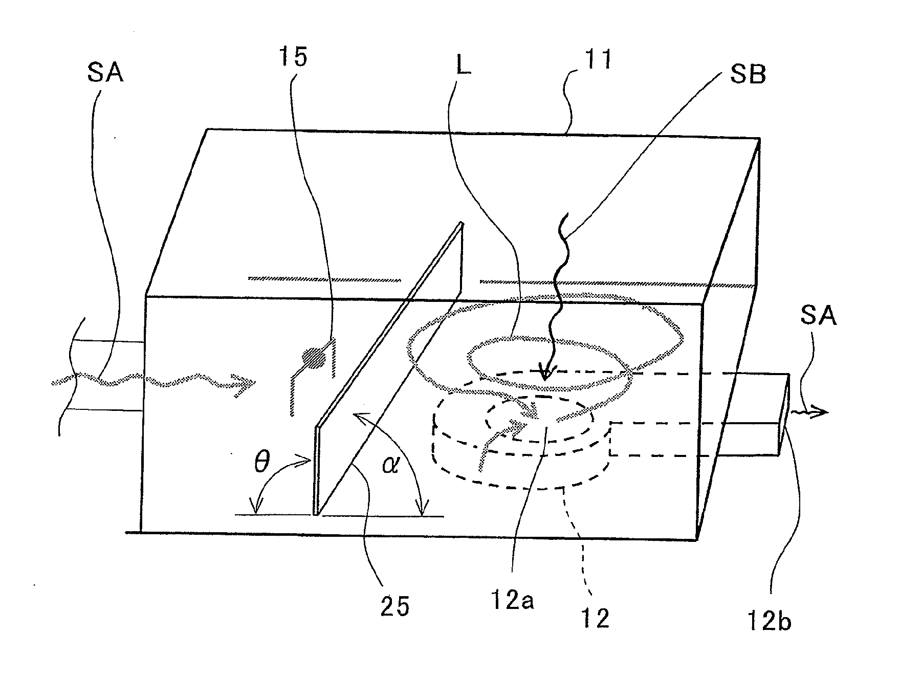
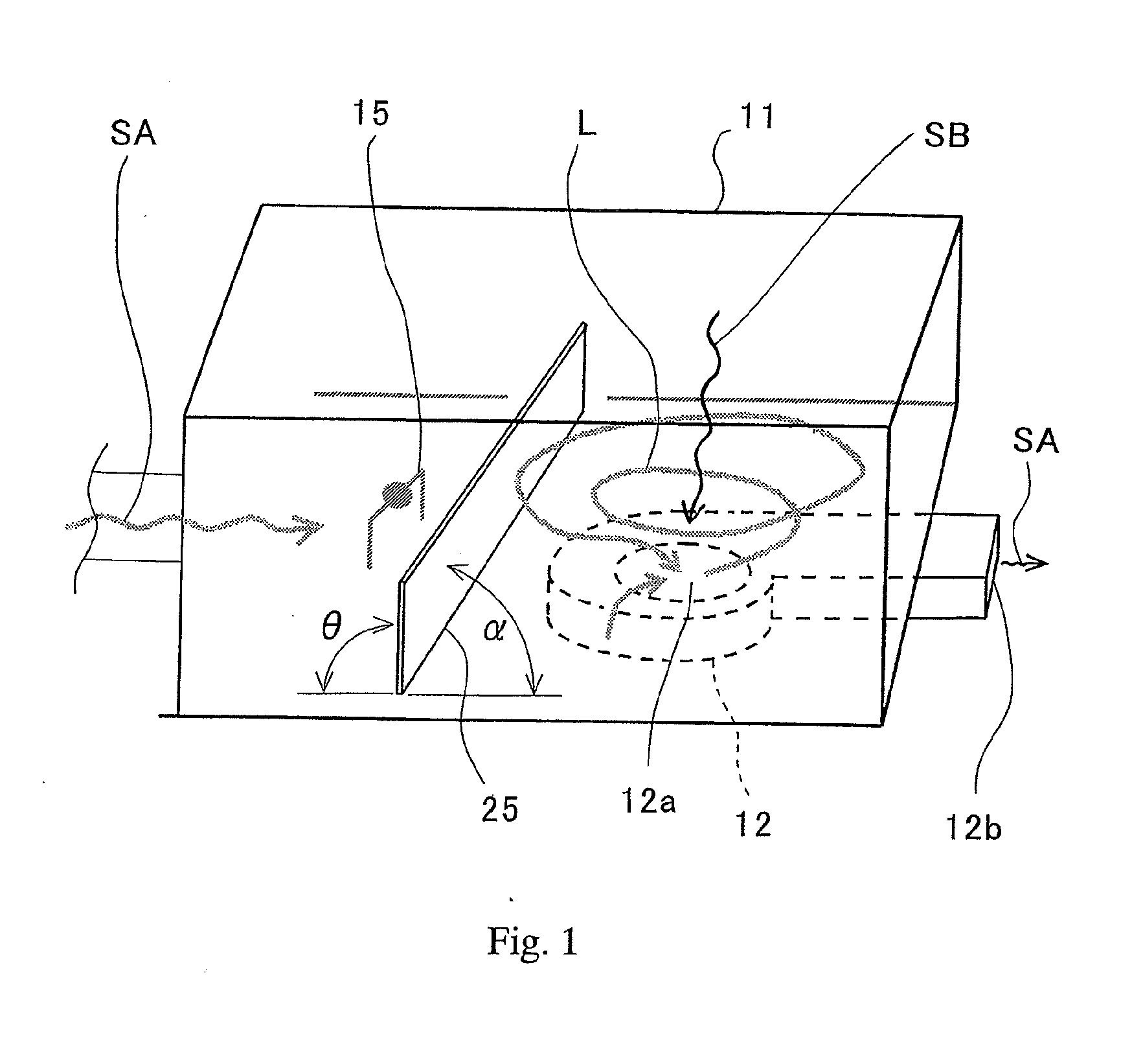
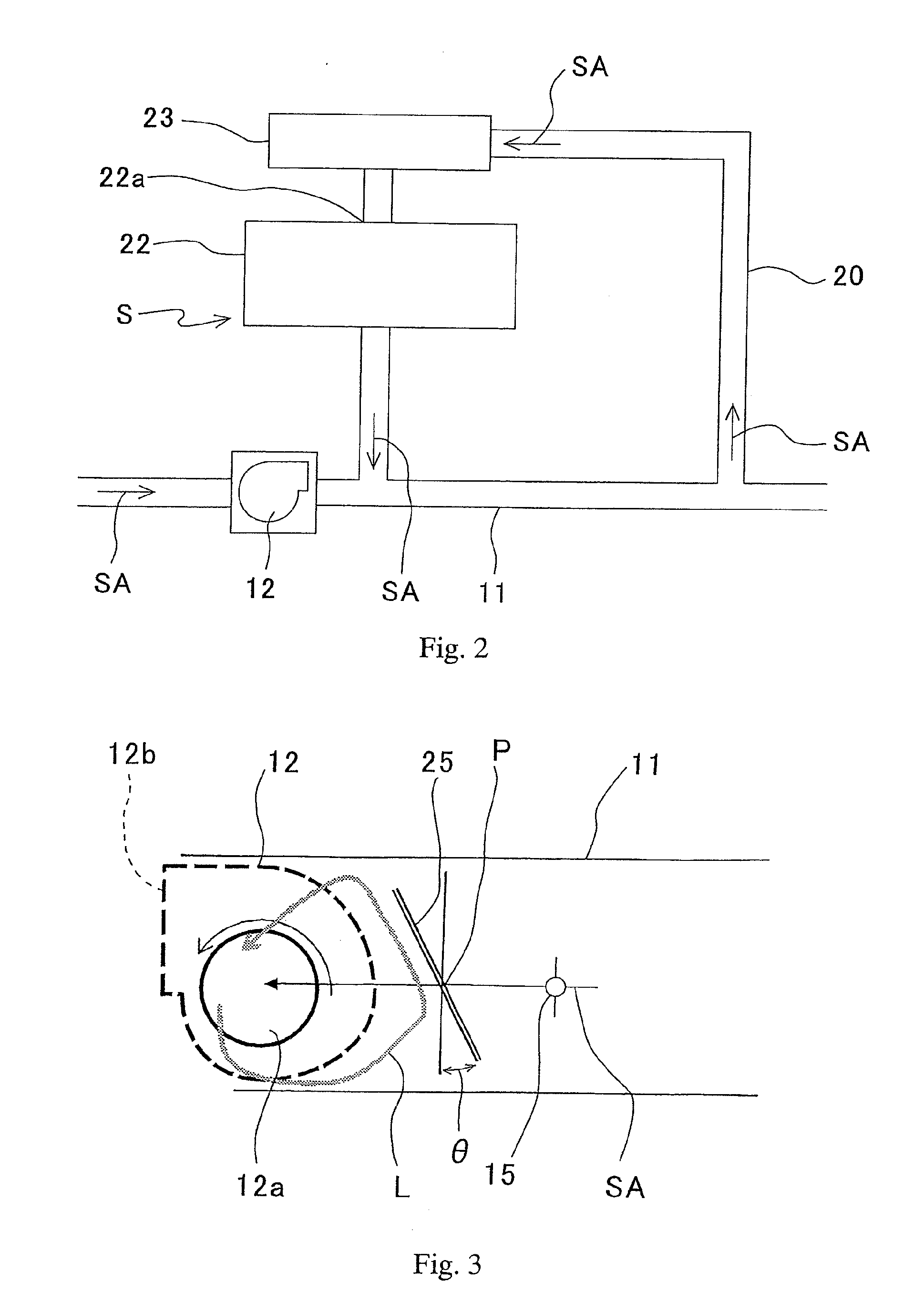
[0041]A smoke detector S includes a smoke detection part 22 connected to a sampling pipe 11 through a pipe 20, a filter 23 disposed at an inflow port 22a side of the smoke detection part 22, a fan (blower fan) 12 that sucks sampling air SA into the sampling pipe 11, and an air velocity sensor (flow sensor) 15 that measures an air velocity of the sampling air SA within the sampling pipe 11.

[0042]The smoke detection part 22 is provided with a light receiving element (smoke sensor) (not shown) such as a light emitting element and a photodiode, a light trap (not shown), a condenser lens (not shown), an aperture (not shown), and so on.

[0043]Within an inflow part 40 having a substantially box shape, and an intake port (not shown) for the sampling air arranged at a side surface thereof and a suction port 12a of the fan 12 arranged at a bottom surface thereof, an airflow direction of the sampling air SA at a primary si...


PUM


Abstract

To enable an air velocity of sampling air to be precisely measured, a smoke detector (S) includes: a smoke detection part (22) connected to a sampling pipe (11); a fan (12) that sucks sampling air (SA) into the sampling pipe; and an air velocity sensor (15) that measures an air velocity of the sampling air within the sampling pipe. The air velocity sensor (15) is disposed at a primary side of the fan (12), and a straightening vane (25) is disposed between the air velocity sensor (15) and a suction port (12a) of the fan (12).

Description

[0001]This application is a divisional application of application Ser. No. 12 / 382,390, filed Mar. 16, 2009.BACKGROUND OF THE INVENTION[0002]1. Field of the Invention[0003]The present invention relates to a smoke detector that optically detects a contaminant such as smoke caused by fire and floating in the air, and detects the fire.[0004]2. Description of the Related Art[0005]A smoke detector is used for preventing fire or as a detecting system at a time of generation of the smoke or in a semiconductor manufacturing plant or a food factory requiring a certain level of environmental conservation.[0006]The conventional smoke detector includes a smoke detection part connected to a sampling pipe, a fan that sucks sampling air into the sampling pipe, and a wind velocity sensor that measures a wind velocity of the sampling air within the sampling pipe (for example, refer to JP 3714926 B).[0007]In the smoke detector, the sampling air flowing within the sampling pipe is partially introduced ...

Claims


Application Information

Patent Timeline
Patent Type & Authority Applications(United States)
IPC IPC(8): G08B17/10
CPCG08B17/10G08B17/113Y10T137/87571A62C37/08G01N1/22G01N21/53G08B17/107
Inventor YOKOTA, HIROYUKI
Owner NOHMI BOSAI LTD
Why Eureka
Try Eureka