Display device, method of controlling a light emitting diode array of the display device, and computer program product

a technology of display device and light emitting diode array, which is applied in the field of display backlighting, can solve the problems of high cost of current backlighting system, and achieve the effects of reducing the volume of the display device, reducing the depth size or thickness, and reducing the manufacturing cos

Active Publication Date: 2011-08-11
TOP VICTORY INVESTMENTS
View PDF9 Cites 39 Cited by
  • Summary
  • Abstract
  • Description
  • Claims
  • Application Information

AI Technical Summary

Benefits of technology

[0009]Moreover, an idea of the present invention is to utilize at least a part of the circuitry of the display device as circuitry for the backlighting device, thereby reducing the total number of components required for current backlighting systems. The circuitries for a display system and a backlighting device are quite similar. In simplicity, one could say that almost the same components are used as circuitry for the display device and current backlighting devices. The processor, e.g. comprised in a LCD TV, used for processing a video signal and controlling the displaying of image content to the viewer could also be used to process information regarding displaying of backlight. At least part of the components of the circuitry of current display devices has more capacity to perform additional tasks. Hence, at least part of the processing of data regarding the backlighting device may be performed on the circuitry of the display device.
[0013]The display device according to some embodiments provide for lower manufacturing costs and with reduced depth size or thickness compared to current solutions. Accordingly, the volume of the display device is also reduced.

Problems solved by technology

However, current backlighting systems are quite expensive and therefore there is a need of providing backlighting systems with reduced costs.

Method used


Image

  • Display device, method of controlling a light emitting diode array of the display device, and computer program product
  • Display device, method of controlling a light emitting diode array of the display device, and computer program product
  • Display device, method of controlling a light emitting diode array of the display device, and computer program product

Examples


Embodiment Construction

[0035]Several embodiments of the present invention will be described in more detail below with reference to the accompanying drawings in order for those skilled in the art to be able to carry out the invention. The invention may, however, be embodied in many different forms and should not be construed as limited to the embodiments set forth herein. Rather, these embodiments are provided so that this disclosure will be thorough and complete, and will fully convey the scope of the invention to those skilled in the art. The embodiments do not limit the invention, but the invention is only limited by the appended patent claims. Furthermore, the terminology used in the detailed description of the particular embodiments illustrated in the accompanying drawings is not intended to be limiting of the invention.

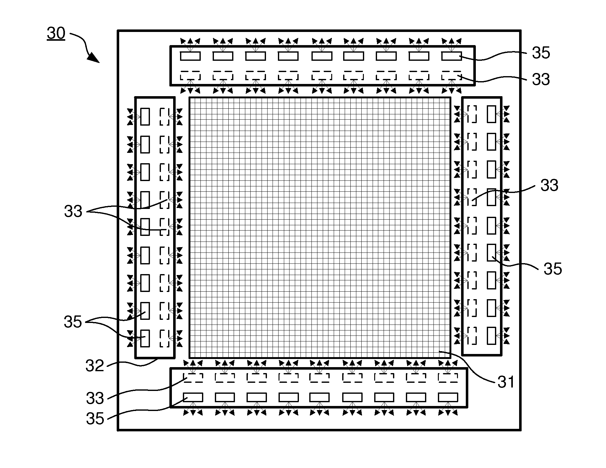
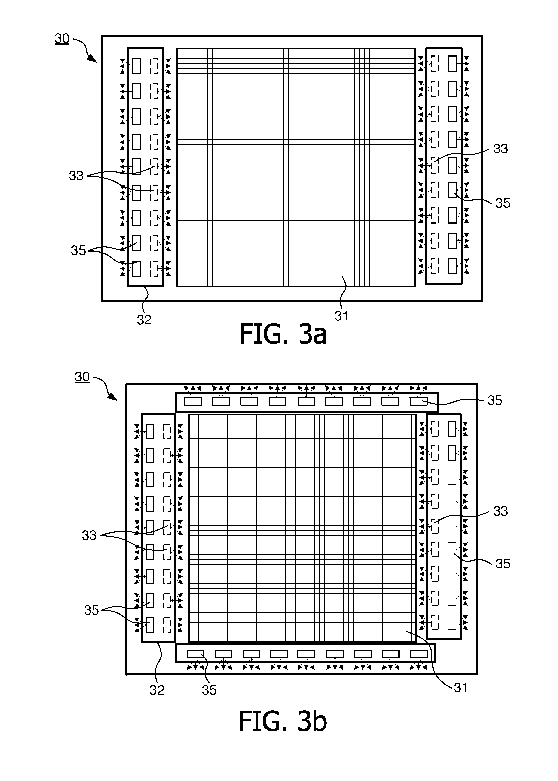
[0036]In current backlighting systems, the display device, such as a TV, and the device providing backlight towards the user or backwards, e.g. onto a wall behind the display device, a...


PUM

PropertyMeasurementUnit
transparentaaaaaaaaaa
brightnessaaaaaaaaaa
coloraaaaaaaaaa

Abstract

A display device (10, 20, 30) is provided, the display device (10, 20, 30) comprising an LED array (33, 35, 12) working both as a backlight source for an LCD panel (31) and as an ambient light source providing ambient light with properties dependent on the image content presented by the LCD panel (31). A corresponding method and computer program product is also provided.

Description

FIELD OF THE INVENTION[0001]This invention pertains in general to the field of display backlighting. More particularly the invention relates to a backlighting device, system, and method.BACKGROUND OF THE INVENTION[0002]Visual display devices are well known and include cinematic film projectors, television sets, monitors, plasma displays, liquid crystal display LCD televisions, monitors, and projectors etc. Such devices are often employed to present images or image sequences to viewer.[0003]The field of backlighting began in the 1960s due to the fact that televisions require a “darker” room for optimal viewing. Backlighting is in its simplest form white light, emitted from e.g. a light bulb, projected on a surface behind the visual display device. Backlighting has been suggested to be used to relax the iris and reduce eye strain.[0004]During recent years the backlighting technology has become more sophisticated and there are several display devices on the market with integrated backl...

Claims


Application Information

Patent Timeline
Patent Type & Authority Applications(United States)
IPC IPC(8): G02F1/1335H05B44/00
CPCG02F1/133603H05B33/086H04N9/73G02F1/133615H05B45/20H04N5/64G02F1/133602G02F1/1333
Inventor BRUYNEEL, FILIPHOEBEECK, CHRISTOPHEPEETERS, ALFREDSEYNAEVE, DIRCK
Owner TOP VICTORY INVESTMENTS
Why Eureka
Try Eureka