Distance measuring system and distance measuring method

a distance measurement and distance measurement technology, applied in distance measurement, surveying and navigation, instruments, etc., can solve the problem that the rangefinding system does not perform processing in view of the effects of ambient light, and achieve the effect of narrowing increasing the dynamic range of the rangefinding system, and increasing measurement accuracy

Active Publication Date: 2011-08-11
HONDA MOTOR CO LTD
View PDF10 Cites 37 Cited by
  • Summary
  • Abstract
  • Description
  • Claims
  • Application Information

AI Technical Summary

Benefits of technology

[0021]According to the present invention, the dynamic range of the rangefinding system is increased together with increasing measurement accuracy. More specifically, according to the present invention, a reflected light incident period, which represents a period during which reflected light is exposed to a photodetector of the light-detecting device within the measuring cycle, is calculated based on a ratio of the measured reflected light energy and the reflected light reference energy, and a ratio of the reflected light incident period and the reference period. As the distance between the rangefinding system and the object become smaller, the reflected light incident period is made shorter, whereas, as the distance becomes greater, the reflected light incident period is made longer. Generally, assuming the same object is involved, as the distance becomes smaller, the intensity of light reflected from the object becomes greater, whereas, as the distance becomes greater, the intensity light reflected by the object becomes smaller. Consequently, if the distance is comparatively small, then reflected light of a greater intensity is exposed over a shorter period. On the other hand, if the distance is comparatively great, then reflected light of a smaller intensity is exposed over a longer period. As a result, a change in the cumulative energy of reflected light, which is exposed during the reflected light incident period, is small compared with the change in distance. This implies that it is possible to narrow the dynamic range of the rangefinding system, and therefore, the dynamic range of the rangefinding system can be increased.
[0022]The step of determining the reflected light reference energy may further comprise the steps of determining ambient light reference energy, which represents cumulative light energy of ambient light during a first reference period, determining combined light reference energy, which represents cumulative combined light energy of the ambient light and the reflected light during a second reference period, which has the same length as the first reference period, and calculating the reflected light reference energy during the second reference period by subtracting the ambient light reference energy from the combined light reference energy. The step of determining the measured reflected light energy may further comprise the steps of determining measured ambient light energy, which represents cumulative light energy of the ambient light during a first measuring cycle, determining measured combined light energy, which represents cumulative combined light energy of the ambient light and the reflected light during a second measuring cycle, which has the same length as the first measuring cycle, and calculating the measured reflected light energy during the second reference period by subtracting the measured ambient light energy from the measured combined light energy. Since the cumulative energy of ambient light...

Problems solved by technology

However, the rangefinding system does not perfo...

Method used


Image

  • Distance measuring system and distance measuring method
  • Distance measuring system and distance measuring method
  • Distance measuring system and distance measuring method

Examples


embodiment

A. Embodiment

[0035]A rangefinding system according to an embodiment of the present invention will be described below with reference to the drawings.

1. Arrangement of the Rangefinding System 10:

(1) Overall Arrangement of the Rangefinding System 10:

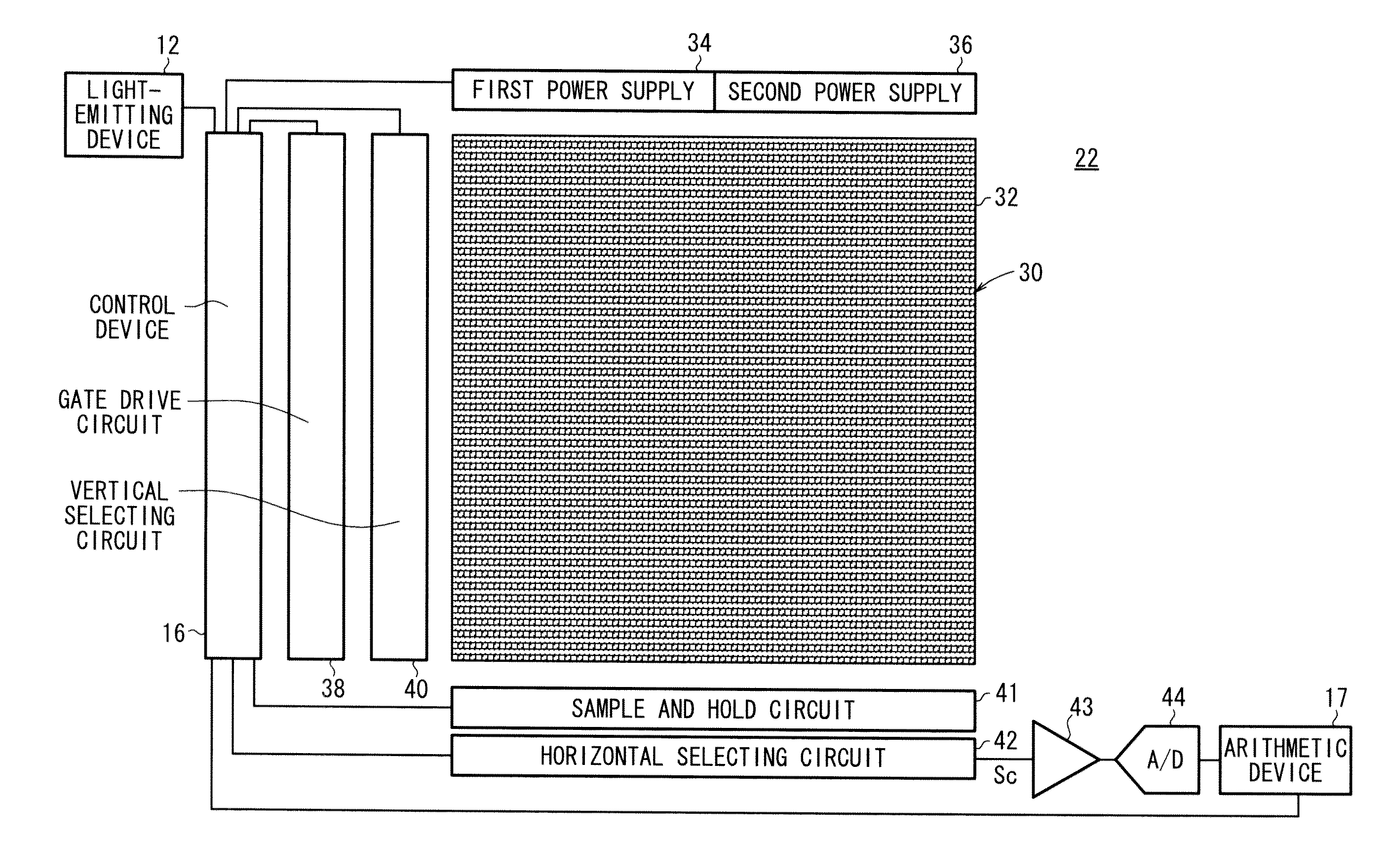
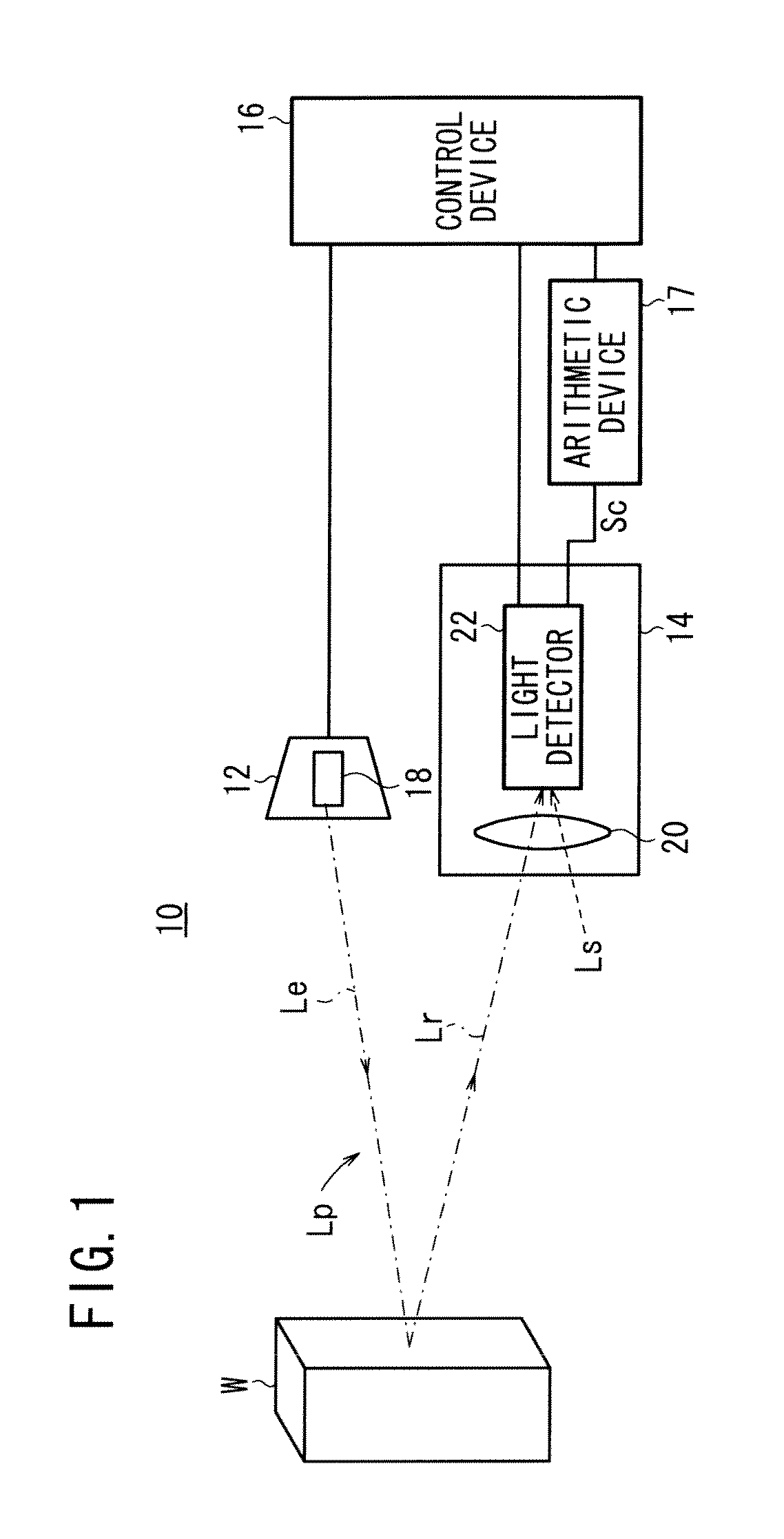
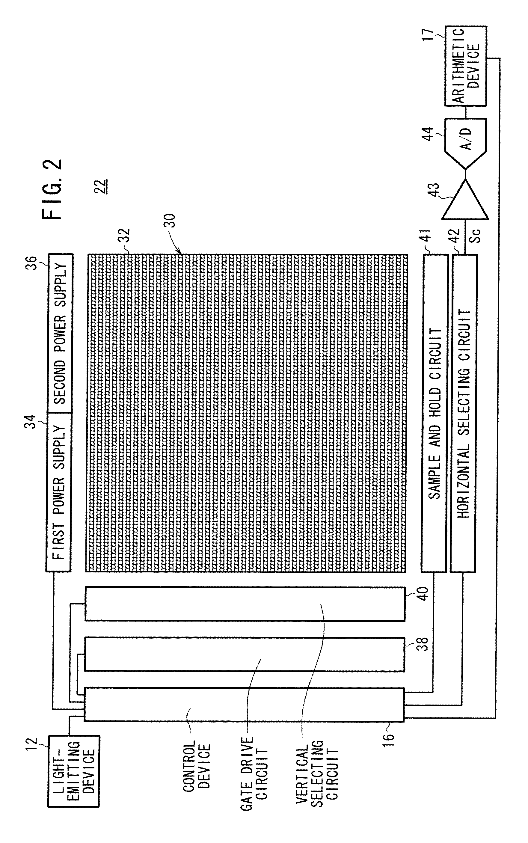
[0036]FIG. 1 is a block diagram of a rangefinding system 10 according to an embodiment of the present invention. The rangefinding system 10 serves to acquire a three-dimensional image using distances that are measured based on output signals from pixels 32 of an image sensor 30, to be described later. The rangefinding system 10 includes a light-emitting device 12, a light-detecting device 14, a control device 16, and an arithmetic device 17. The rangefinding system 10 operates such that, in response to a command from the control device 16, a light emitter 18 of the light-emitting device 12 emits pulsed light Lp, and the pulsed light Lp is reflected by an object W and exposed to the light-detecting device 14. Based on a command from the cont...


PUM


Abstract

A distance measuring system and a distance measuring method which use a time-of-flight (TOF) method. The distance measuring system obtains a reference light quantity of reflected light which is a cumulative light quantity of the reflected light during a reference period, obtains a measured light quantity of the reflected light which is a cumulative light quantity of the reflected light during a measurement period, and calculates, on the basis of a ratio of the measured light quantity of the reflected light to the reference light quantity of the reflected light and a ratio of the reflected light incident period to the reference period, a reflected light incident period that is a period which is included in the measurement period and during which the reflected light is incident upon photoelectric conversion elements of a light-receiving device. Then, the distance measuring system calculates the distance between the distance measuring system and an object on the basis of the reflected light incident period.

Description

TECHNICAL FIELD[0001]The present invention relates to a rangefinding (distance measuring) system and to a rangefinding (distance measuring) method, which employ a time-of-flight (TOF) process.BACKGROUND ART[0002]One known rangefinding system for measuring a distance up to an object in a contactless manner employs a time-of-flight (TOF) process. According to such a TOF process, light that is emitted toward an object, and a period of time consumed after the light is emitted toward the object and until the light bounces off the object and returns, are measured, whereby the distance up to the object can be measured based on the period of time and the velocity of light (see Japanese Laid-Open Patent Publication No. 2001-281336, U.S. Pat. No. 5,754,280, and Ryohei Miyagawa and Takeo Kanade “CCD-Based Range-Finding Sensor,” IEEE Transactions on Electron Devices, Vol. 44, No. 10, October 1997, pp. 1648-1652 (hereinafter referred to as the “Miyagawa paper”).[0003]The Miyagawa paper contains ...

Claims


Application Information

Patent Timeline
IPC IPC(8): G01C3/08G01S17/10G01S17/894
CPCG01C3/08G01S7/4876G01S17/89G01S17/10G01S17/894
Inventor KAMIYAMA, TOMOYUKI
Owner HONDA MOTOR CO LTD
Why Eureka
Try Eureka