Co-cured sheath for composite blade

a composite blade and sheath technology, applied in the direction of machines/engines, other domestic objects, liquid fuel engines, etc., can solve the problems of secondary damage downstream of the blades and high cost of the process

Inactive Publication Date: 2011-08-11
UNITED TECH CORP
View PDF18 Cites 102 Cited by
  • Summary
  • Abstract
  • Description
  • Claims
  • Application Information

AI Technical Summary

Problems solved by technology

Impact of large foreign objects can rupture or pierce the blades and cause secondary damage downstream of the blades.
While this process is costly, it

Method used


Image

  • Co-cured sheath for composite blade
  • Co-cured sheath for composite blade
  • Co-cured sheath for composite blade

Examples


Embodiment Construction

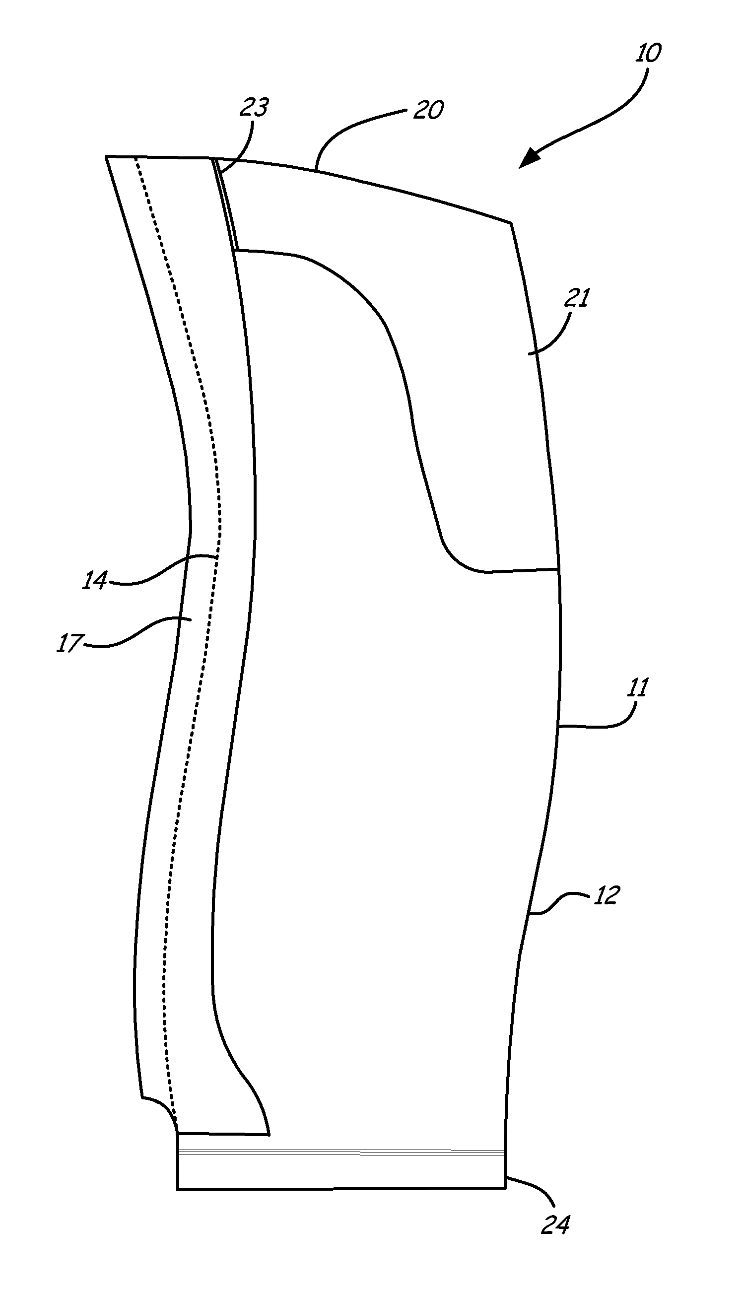
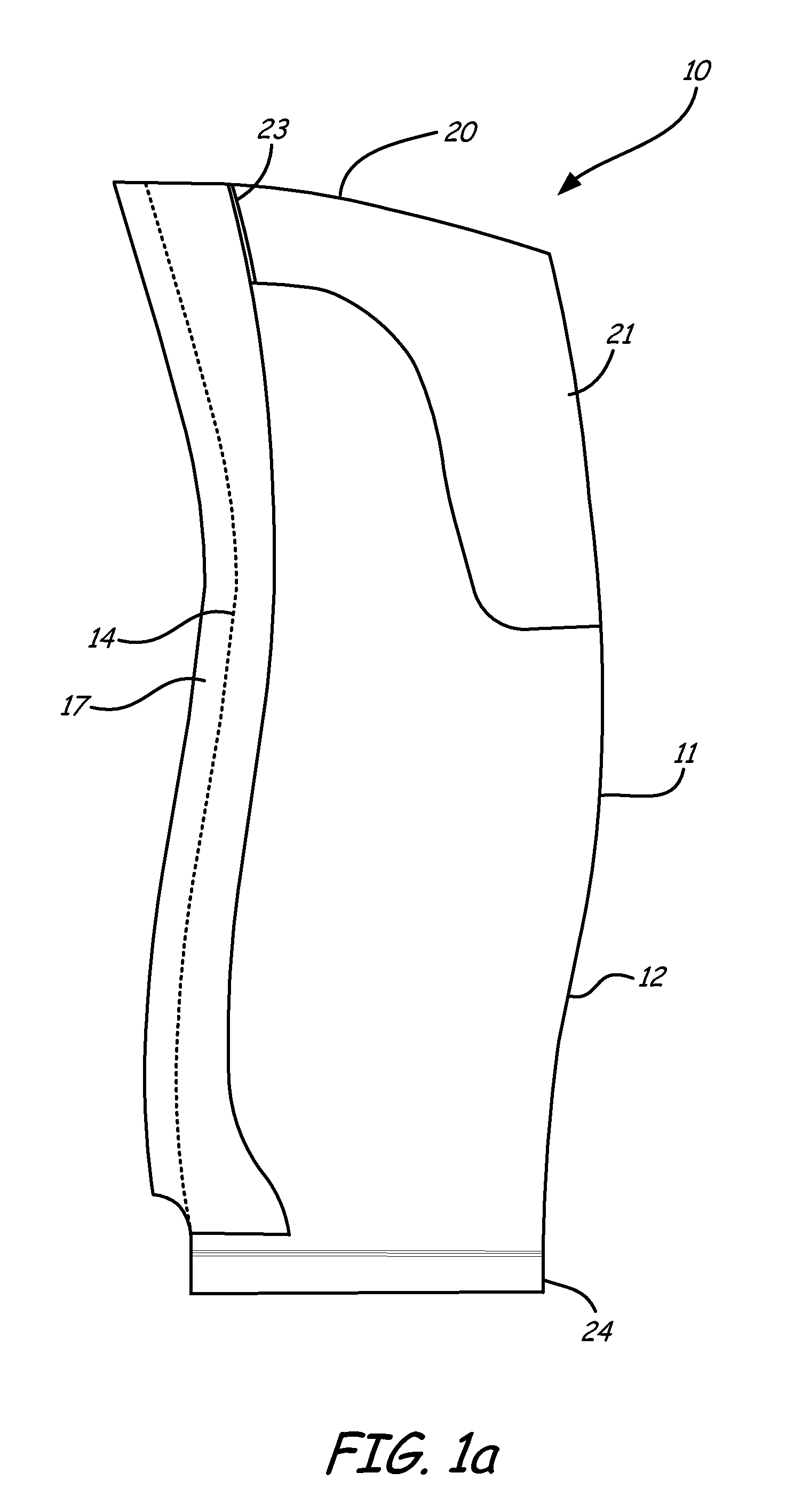
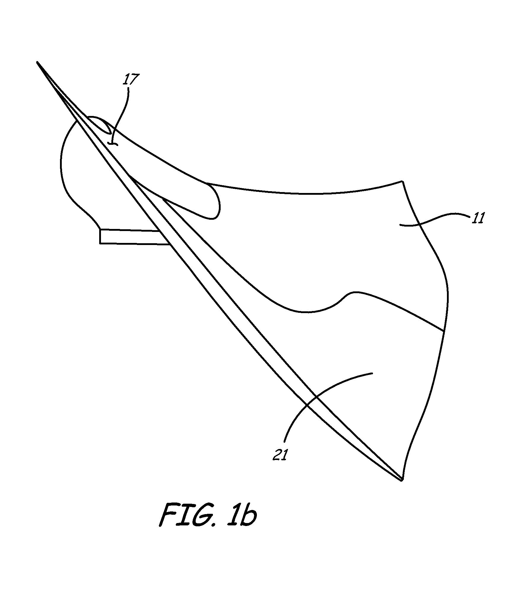
FIGS. 1a and 1b illustrate composite blade 10 having trailing edge 12, leading edge 14, sheath 17, tip 20, and root 24. Root 24 is illustrated as a dovetail root. However, root 24 can have any configuration that is used in blade assemblies. Sheath 17 is bonded to its leading edge 14 using the process of this invention in which the dry composite blade 10 and the sheath 17 are placed in a mold and cured at the same time, as described hereinafter. Blade 10 is a composite perform made from a woven three dimensional center core with laid on filament plies as describe below. Alternatively the composite may be simply a woven three dimensional core or a plurality of filament plies. Also used in the present invention are blades such as helicopter or propellers that have a foamed center or honeycomb center to lighten the weight of the blade. Any kind of composite blade that can be resin molded from a dry perform is part of this invention. The method of this invention may be used with any blad...


PUM


Abstract

A method of forming a composite blade having a sheath on a portion of the blade by placing the dry composite blade and sheath in a mold, adding a resin, and curing the resin to integrally bond the blade to the metal sheath. The portion of the blade having the sheath bonded thereto may be at least one of the leading edge, the tip and the trailing edge of the blade.

Description

BACKGROUNDComposite materials offer potential design improvements in gas turbine engines. For example, in recent years composite materials have been replacing metals in gas turbine engine fan blades because of their high strength and low weight. Most metal gas turbine engine fan blades are titanium. The ductility of titanium fan blades enables the fan to ingest a bird and remain operable or be safely shut down. The same requirements are present for composite fan blades.A composite airfoil for a turbine engine fan blade can have a sandwich construction with a carbon fiber woven core at the center and two-dimensional filament reinforced plies or laminations on either side. To form the composite airfoil, individual two-dimensional plies are cut and stacked in a mold with the woven core. The mold is injected with a resin using a resin transfer molding process and cured. The plies vary in length and shape. The carbon fiber woven core is designed to accommodate ply drops so that multiple ...

Claims


Application Information

Patent Timeline
IPC IPC(8): F01D5/14B29C45/14
CPCB29C70/48B29C70/78F01D5/282F04D29/023F04D29/324F05D2300/702F05D2240/303Y02T50/672F05D2220/36B29L2031/082F05D2240/121B29C70/86F05D2300/44F05D2230/23F05D2230/53F05D2300/603Y02T50/60F01D5/147F01D5/288F05D2300/133
Inventor PARKIN, MICHAELHUTH, BRIAN P.BEDARD, WILLIAM M.
Owner UNITED TECH CORP
Why Eureka
Try Eureka