Electric fan

a technology of electric fans and fans, applied in the direction of positive displacement liquid engines, piston pumps, liquid fuel engines, etc., can solve the problem of limiting and achieve the effect of enhancing the waterproof performance of conventional structures

Inactive Publication Date: 2011-08-11
SANYO DENKI CO LTD
View PDF8 Cites 11 Cited by
  • Summary
  • Abstract
  • Description
  • Claims
  • Application Information

AI Technical Summary

Benefits of technology

[0003]There is a limit to enhancing waterproof performance of a conventional structure for preventing entry of the liquid into the receiving space even if a clearance is provided to form a labyrinth structure as mentioned above.
[0004]Further, when the clearance forming the labyrinth structure is defined, dimensional tolerances of the casing and the impeller are reduced. Thus, assembly accuracy of the impeller body and the casing of the electric fan needs to be increased.
[0005]An object of the present invention is to provide an electric fan in which waterproof performance may be enhanced by using a labyrinth structure which prevents a liquid from entering into a receiving space to receive a stator and a rotor, as compared with conventional electric fans.
[0006]Another object of the present invention is to provide an electric fan including a labyrinth structure by which waterproof performance may not be reduced so significantly as in conventional electric fans even if assembly accuracy of the electric fan is lower than that in conventional electric fans.
[0009]Since the one or more volume expanding portions are formed within the clearance which forms the labyrinth structure in the present invention, the liquid which has entered into the clearance pools in the one or more volume expanding portions. Then, after the one or more volume expanding portions have been filled with the liquid, the liquid goes further toward the receiving space. As a result, a period of time until the liquid enters into the receiving space is longer than that in the conventional structure, thereby enhancing the waterproof performance according to the present invention. Further, by providing the one or more volume expanding portions, the volume of the entire labyrinth structure may be increased more than the conventional structure, thereby enhancing the waterproof performance. Accordingly, dimensional tolerances of the casing and the impeller do not need to be reduced so much as in conventional structures in order to enhance the waterproof performance. Even if assembly accuracy of the electric fan is lower than those of conventional structures, the waterproof performance is not significantly reduced.

Problems solved by technology

There is a limit to enhancing waterproof performance of a conventional structure for preventing entry of the liquid into the receiving space even if a clearance is provided to form a labyrinth structure as mentioned above.

Method used


Image

  • Electric fan
  • Electric fan
  • Electric fan

Examples


first embodiment

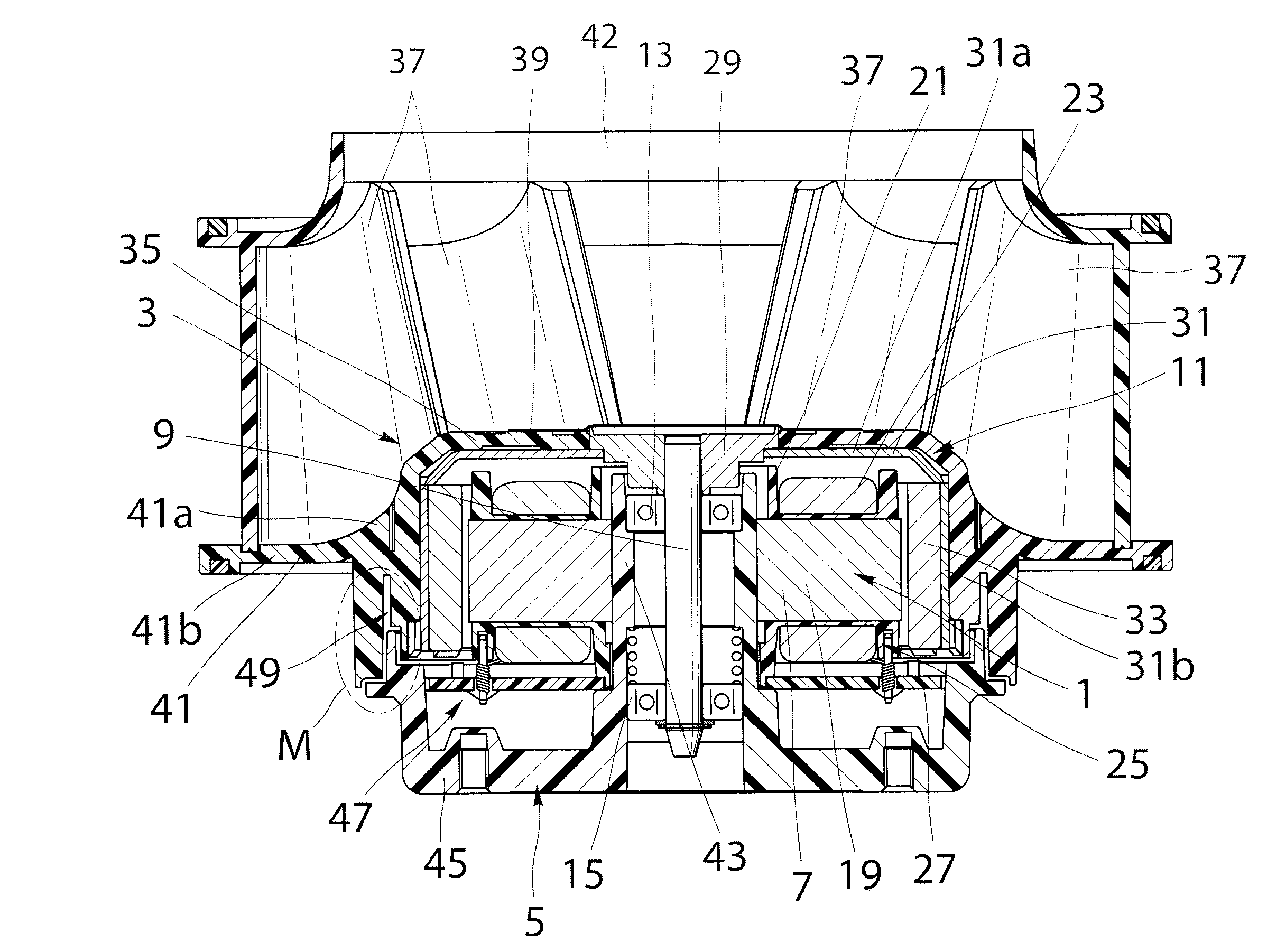
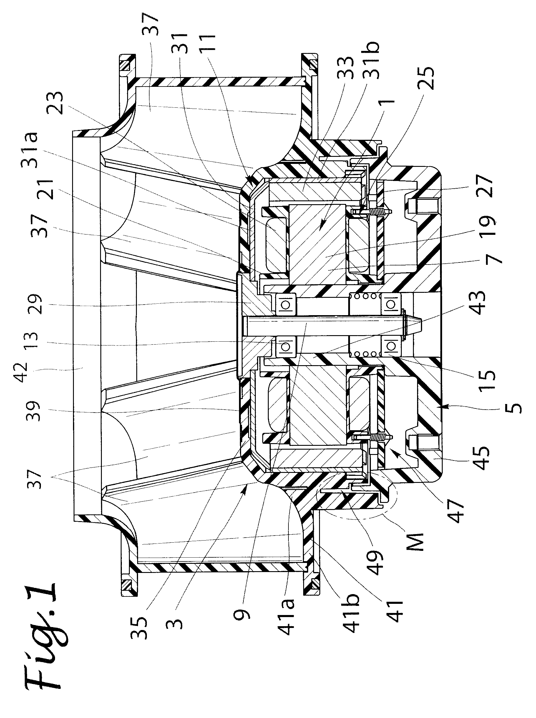
[0021]Embodiments of the present invention will be described below in detail with reference to the drawings. FIG. 1 is a sectional view of an electric fan in the present invention applied to a centrifugal fan. FIG. 2 is a partially enlarged view of a portion indicated by reference sign M in FIG. 1. The electric fan of this embodiment comprises an electric motor 1, an impeller 3 made of a synthetic resin and configured to be rotated by the electric motor 1, and a casing 5 for partially receiving components of the electric motor 1. The electric motor 1 includes a stator 7 and a rotor 11 configured to rotate outside the stator 7, centering on a rotary shaft 9. The stator 7 is mounted on a bearing holder 43 in which two ball bearings 13 and 15 for rotatably supporting the rotary shaft 9 are fitted and held. The stator 7 comprises a stator core 19 disposed outside this bearing holder 43, an insulator 21 made of an insulating resin and fitted with the stator core 19, and stator windings 2...

second embodiment

[0027]FIG. 3 is a sectional view of an electric fan in the present invention applied to a centrifugal fan. FIG. 4 is a partially enlarged view of a portion indicated by reference sign M shown in FIG. 3. Though dimensions and shapes of respective members of the electric fan in this embodiment are different from those of the corresponding members in the electric fan shown in FIGS. 1 and 2, the electric fan of this embodiment has basically the same structure as the electric fan shown in FIGS. 1 and 2 except a cup-like member, a base of a casing, and an impeller body. Therefore, reference numerals calculated by adding 100 to the reference numerals in FIGS. 1 and 2 are assigned to members in FIGS. 3 and 4 which have basically the same structures as those in FIGS. 1 and 2. Descriptions of the members in FIGS. 3 and 4 will thereby be omitted.

[0028]As shown in FIG. 3, the electric fan in this embodiment does not include the cup-like member fixed to the rotary shaft. Rotor magnetic poles 133...

third embodiment

[0031]FIG. 5 is a sectional view of an electric fan in the present invention applied to a centrifugal fan. FIG. 6 is a partially enlarged view of a portion indicated by reference sign M in FIG. 5. Though dimensions and shapes of respective members are different from those of the corresponding members in FIGS. 1 and 2, the electric fan of this embodiment has basically the same structure as the electric fan shown in FIGS. 1 and 2 except the configuration of a groove portion for expanding a clearance. Therefore, reference numerals calculated by adding 200 to the reference numerals in FIGS. 1 and 2 are assigned to members in FIGS. 5 and 6 which have basically the same structures as those in FIGS. 1 and 2. Descriptions of the members in FIGS. 5 and 6 will thereby be omitted.

[0032]In the electric fan of the first embodiment shown in FIGS. 1 and 2, the wall portion 35c of the impeller body 35 located radially inside of the annular groove portion 49a constituting the volume expanding portio...


PUM


Abstract

An electric fan is provided, including a labyrinth structure with increased performance of preventing entry of a liquid into a receiving space to receive a stator and a rotor. A clearance is defined between an opposed wall portion of a base and an opposed wall portion of an impeller body, which are opposed to each other in an axial direction of a rotary shaft, to form a labyrinth structure. The opposed wall portion of the base and the opposed wall portions of the impeller body are shaped to form a volume expanding portion within the clearance. The volume expanding portion is constituted from a groove portion for expanding the clearance, having a volume larger than other portions within the clearance.

Description

TECHNICAL FIELD[0001]The present invention relates to an electric fan such as an axial fan and a centrifugal fan, which uses an electric motor as a driving source.BACKGROUND ART[0002]An electric fan which comprises an impeller and a casing is known. The impeller includes a plurality of blades and is configured to rotate by an electric motor. The casing includes a base which defines a receiving space to receive a stator and a rotor of the electric motor. In such an electric fan, a liquid such as water may enter into the receiving space from between an impeller body of the impeller and the base. In order to cope with this problem, Japanese Patent No. 3694224 (JP3694224), for example, proposes that a clearance be defined between a casing and an impeller of a centrifugal fan to form a labyrinth structure for blocking entry of a liquid into a receiving space.SUMMARY OF THE INVENTION[0003]There is a limit to enhancing waterproof performance of a conventional structure for preventing entry...

Claims


Application Information

Patent Timeline
Patent Type & Authority Applications(United States)
IPC IPC(8): F04B35/04
CPCF04D17/16F04D25/0613F04D25/0646F04D29/083H02K5/10F04D29/059H02K21/22F05D2210/12F05D2240/55Y10S417/00Y10S415/00
Inventor KUDO, NARUHIKOIKEDA, TOMOAKIMARUYAMA, HARUHISA
Owner SANYO DENKI CO LTD
Why Eureka
Try Eureka