
Equipment and method for the forming of paper containetrs

a technology of containetrs and equipment, applied in the field of equipment and method for the forming of containetrs, can solve the problems of unsuitable for diversified strokes, considerable down time and equipment costs, etc., and achieve the effect of saving down time and improving the productivity of the forming system

Active Publication Date: 2011-08-11
QUALITY TOOLS SRL
View PDF4 Cites 19 Cited by
  • Summary
  • Abstract
  • Description
  • Claims
  • Application Information

AI Technical Summary

Benefits of technology

"The invention proposes equipment and a method for making paper containers in one go, from roughing the paper to forming the container and finishing its rim. This eliminates the need for extra equipment and increases productivity by allowing for faster production. The equipment includes a mobile mold holder table with a cutting blade, pleating / crimping ring, and rim former, and a fixed semi-mold with a counter cutting blade, pleating / crimping ring, and rim former. The blade and counter blade cut the paper, the pleating / crimping rings pleat and crimp the paper, and the rim former forms a crimped rim. The method involves using the equipment to form containers, trays, or tubs."

Problems solved by technology

In other words, the container, therefore, is not made, as they say, “all in one go”, but in successive and separate phases: first with equipment for cutting the initial roughing card, then with the equipment for forming the container starting from the pre-established roughing card with considerable down time and equipment costs.
Furthermore, also not expressly described, the machine represented in the abovementioned document is purely mechanical and as such it does not appear to be suitable for carrying out diversified strokes for the realization of different work, especially if in the presence of damp paper.

Method used


Image

  • Equipment and method for the forming of paper containetrs
  • Equipment and method for the forming of paper containetrs
  • Equipment and method for the forming of paper containetrs

Examples


Embodiment Construction

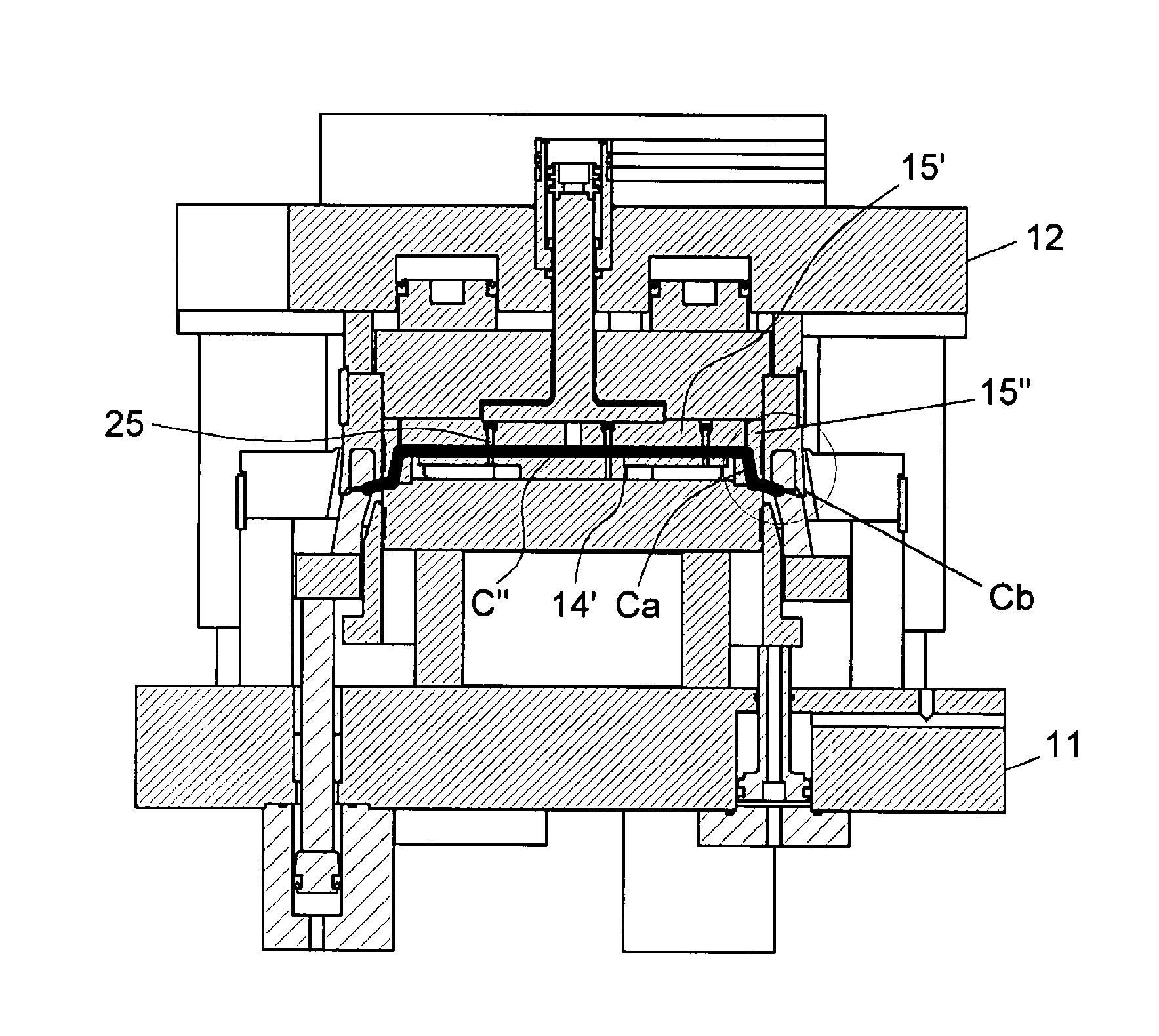
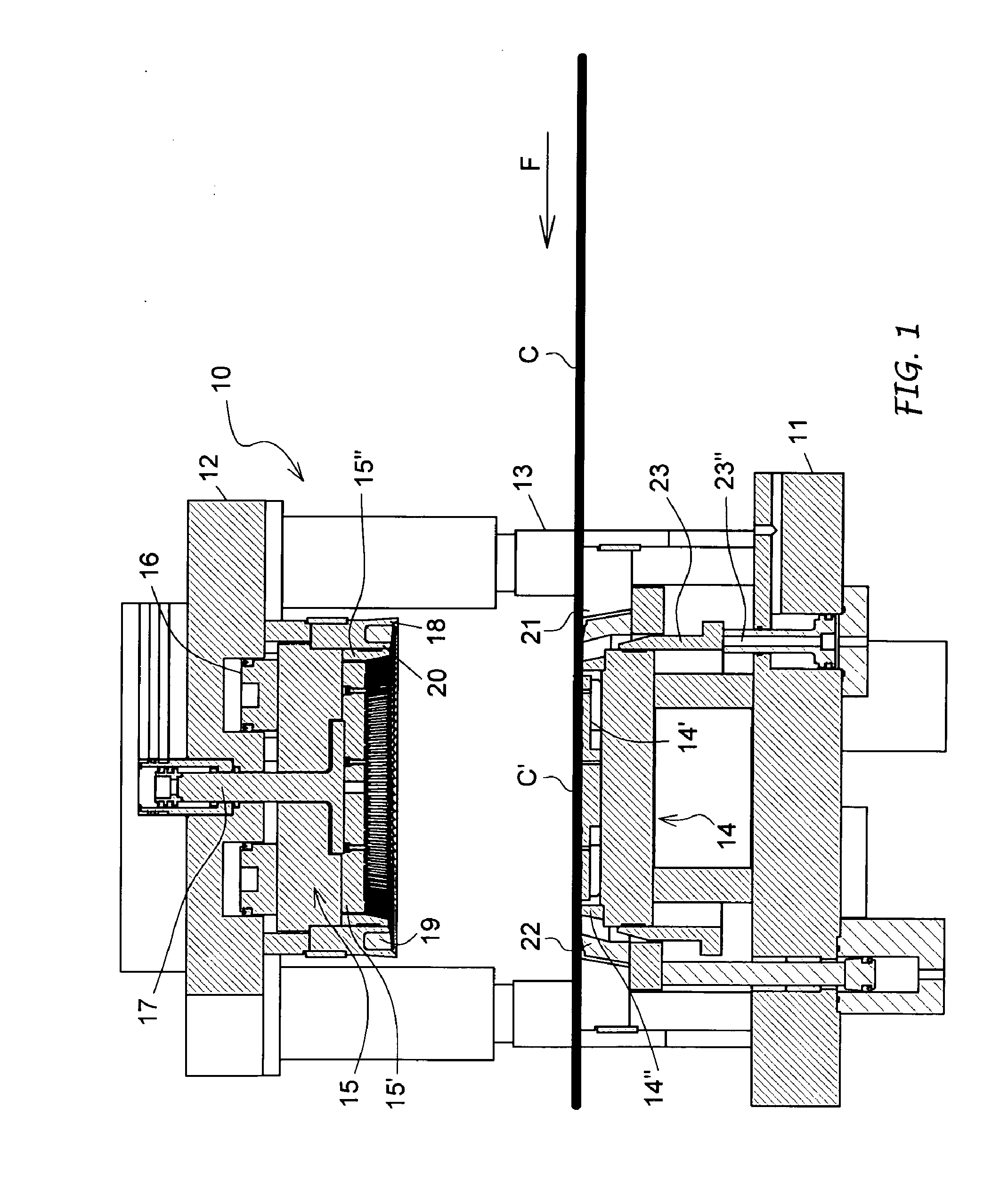
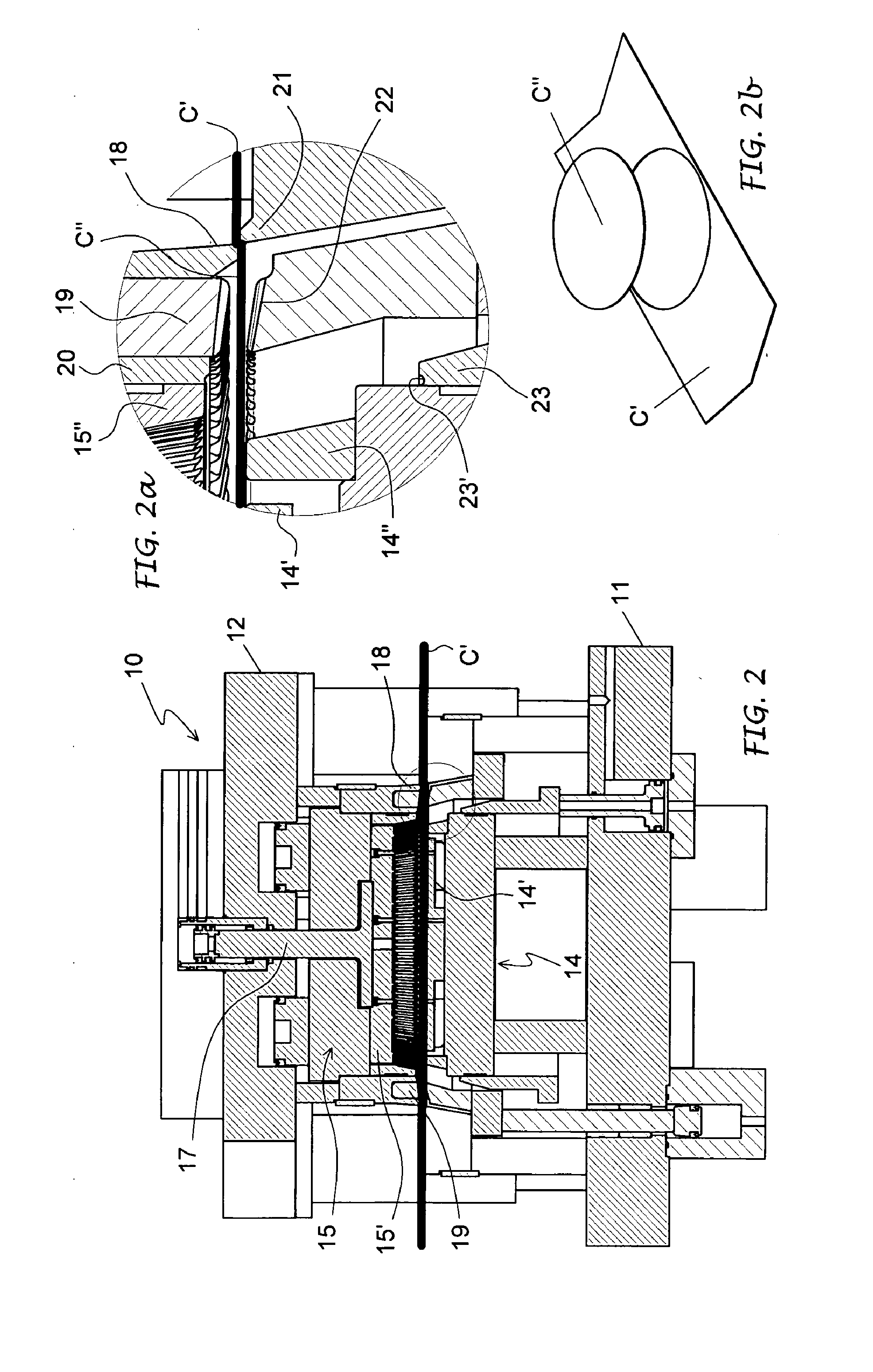
[0028]In said drawings, the equipment for the forming of paper containers of the type referred to above and globally indicated by 10, is usable with a press, in particular, but not exclusively, of the type described in the above application for a patent by the same applicant and can be fed with a continuous paper tape C according to the F arrows in FIG. 1.

[0029]The equipment 10 basically comprises a fixed semi-mould holder lower table 11 and an upper mould holder table 12, the latter movable along guide columns 13 above the fixed table. From time to time the fixed mould holder table 11 is attached to a lower semi-mould 14, whereas the mobile mould holder table 12 becomes attached to an upper semi-mould 15 with the interposition of a shock absorber bearing 16, the two semi-moulds 14, 15 defining complementarily at least an imprint corresponding, in shape and dimensions, to the container 100 to be made.

[0030]The initial paper C is wetted according to the requirements and the component...


PUM


Abstract

The invention concerns the equipment for forming of paper containers starting from a continuous wet paper belt. It comprises a mobile semi-mould and a fixed semi-mould defining an impression corresponding to the container to be produced. Around the mobile semi-mould (15) are provided concentrically an upper cutting blade (18), an upper pleating / crimping ring (19) and an upper rim former (20); around the fixed semi-mould (14) are provided a counter cutting blade (21), an upper counter pleating / crimping ring (22) and a counter rim former (23), associated respectively with the cutting blade, the pleating / crimping ring and rim former on board associated with a mobile semi-mould. And this, respectively, to cut from the initial paper tape a length of paper depending on the measurements of the container to be formed, to pleat / crimp a peripheral crown of said blank paper during the closing stroke of the semi-moulds, and to form a crimped rim around the lateral wall of the container during the opening stroke of said semi-moulds.

Description

FIELD OF THE INVENTION[0001]The invention refers to equipment to be used with presses for the forming of paper containers provided with a curled peripheral rim. The invention is also concerns a method for the forming of containers with such equipment, meaning here by “containers”, trays and circular or non circular tubs made out of a “papery material”, both vellum paper (VP) and paper using several layers or siliconed, also with a weight of less than about 220 g / m2.STATE OF THE TECHNIQUE[0002]On the one hand the document U.S. Pat. No. 6,093,460 is indicative of the state of the technique. That document describes a machine and a method for forming the so-called basically rectangular paper containers, starting however from a pre-cut initial intermediate forging not carried out by the machine, but in a previous work station, and using explicitly card with a relatively high weight (from 200 to 400 g / m2) and covered by a resin film both on all its front and rear surfaces.[0003]In other w...

Claims


Application Information

Patent Timeline
Patent Type & Authority Applications(United States)
IPC IPC(8): B31B1/44B31B50/44B31B50/59
CPCB31B43/00B31B45/00B31B2201/223B31F1/0077B31B2201/2695B31B2203/00B31B2201/2654B31B50/44B31B2100/00B31B2110/10B31B2110/20B31B2120/70B31B50/592
Inventor TRECCANI, GIUSEPPELEALI, MAURO
Owner QUALITY TOOLS SRL
Learn More