Method and device for unbalance correction on a vehicle wheel

a vehicle wheel and unbalance technology, applied in the direction of manufacturing tools, instruments, transportation and packaging, etc., can solve the problem of requiring plenty of time for unbalance correction, and achieve the effect of reducing the cycle tim

Active Publication Date: 2011-08-18
SCHENCK ROTEC GMBH
View PDF26 Cites 25 Cited by
  • Summary
  • Abstract
  • Description
  • Claims
  • Application Information

AI Technical Summary

Benefits of technology

[0024]To reduce the cycle time, the device of the invention may further include two balancing stations both of which are located in the working range of the handling device. Moreover, a transfer station may be provided which is connected to the unbalance measuring station by a conveying device constructed to transfer a vehicle wheel from the unbalance measuring station to the transfer station without changing its angular position.
[0025]Still further, the device of the...

Problems solved by technology

The known method is configured for unbalance correction in only one pl...

Method used


Image

  • Method and device for unbalance correction on a vehicle wheel
  • Method and device for unbalance correction on a vehicle wheel
  • Method and device for unbalance correction on a vehicle wheel

Examples


Embodiment Construction

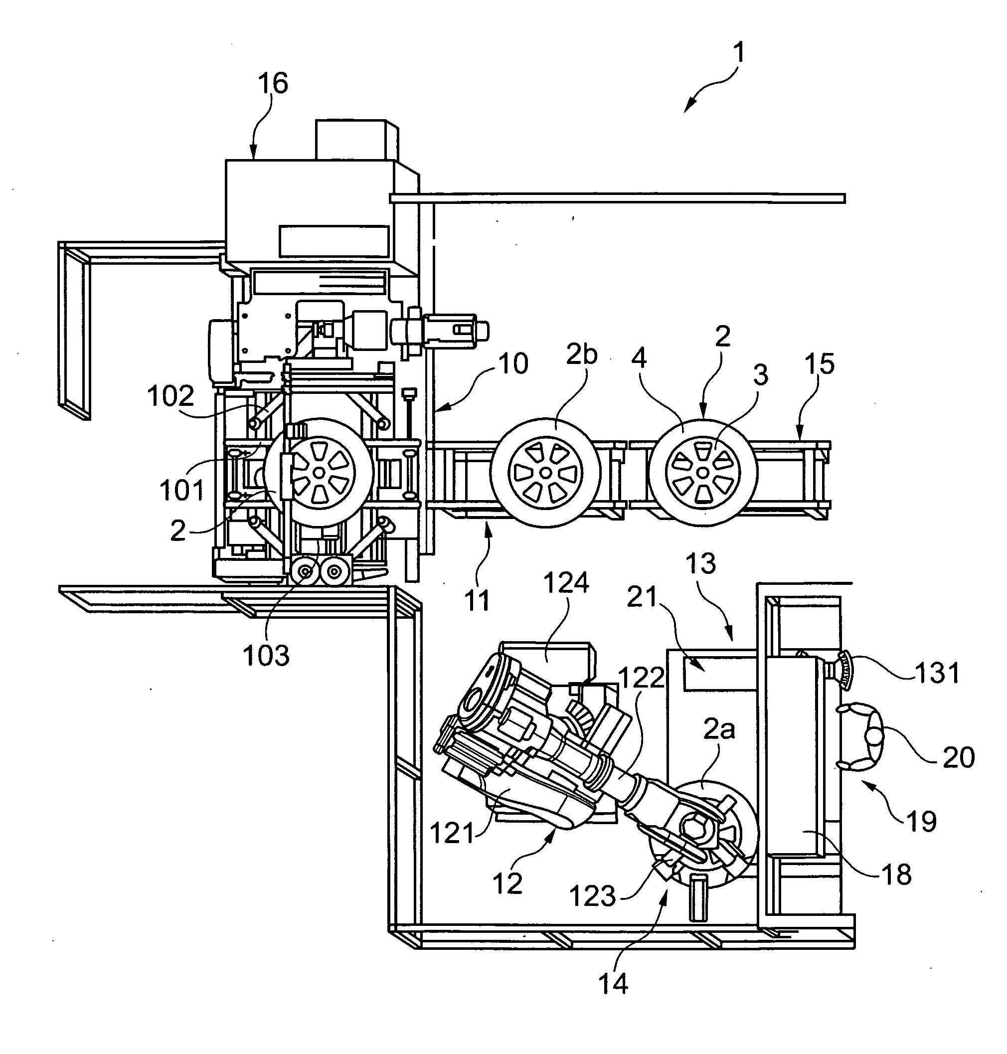
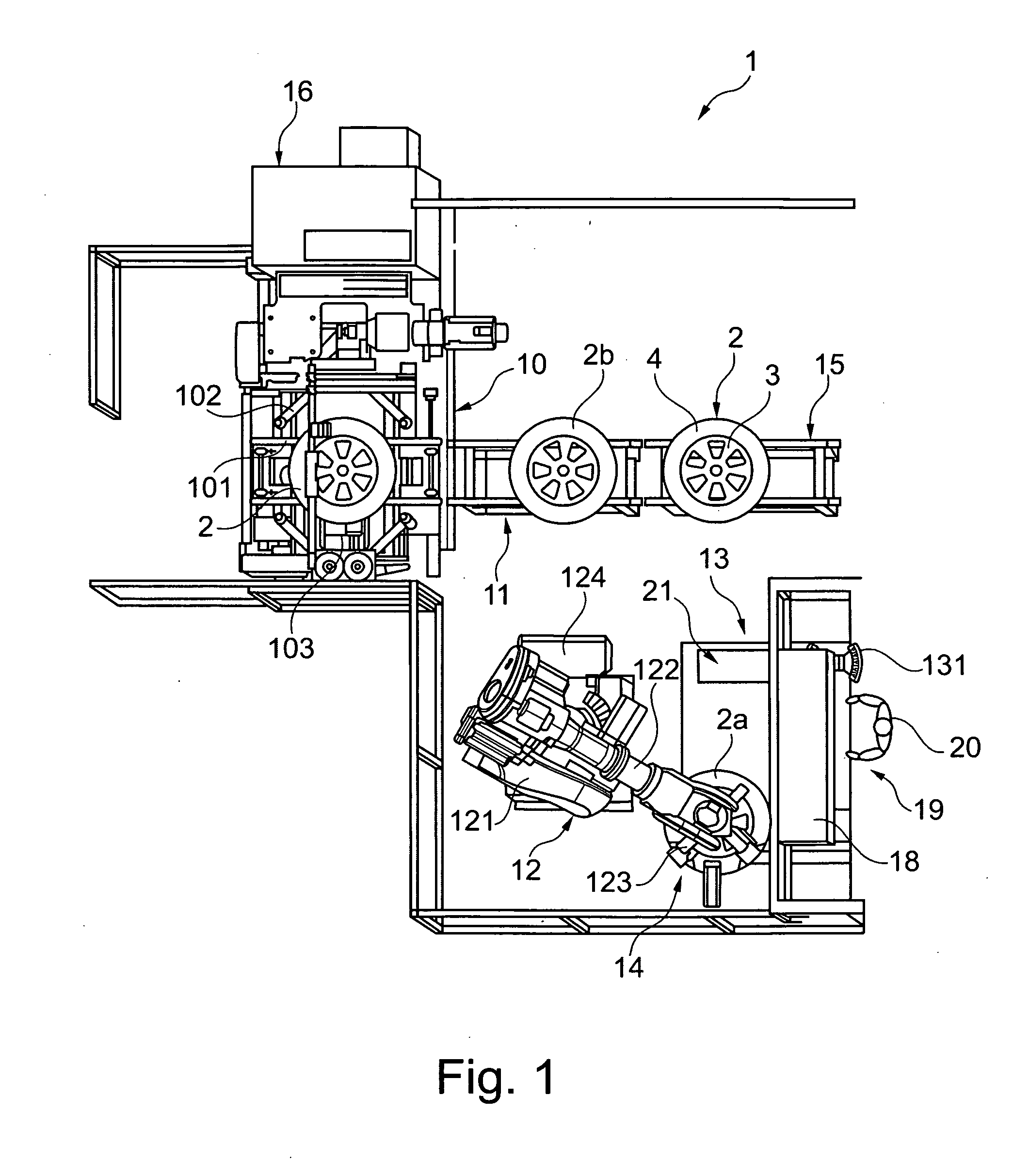
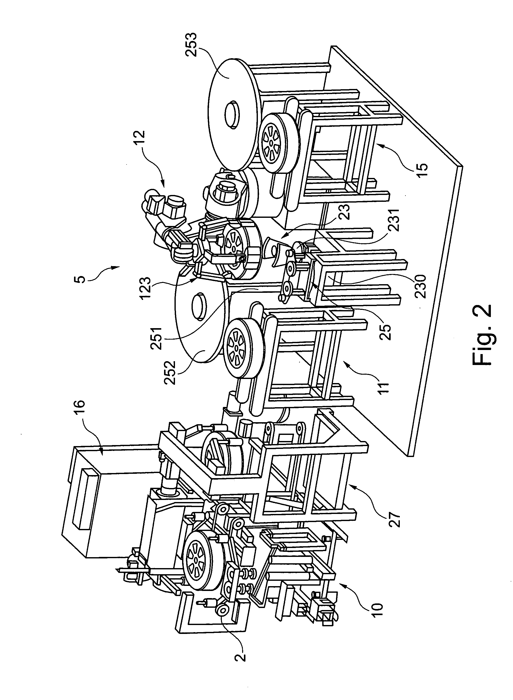
[0034]The installation 1 shown in FIG. 1 is part of a production line for the manufacture of complete vehicle wheels 2 essentially comprised of a rim 3 and a tire 4 surrounding the rim 3. The vehicle wheels 2 are assembled in an assembly line and then fed to the installation 1 by means of a conveyor unit. The installation 1 comprises an unbalance measuring station 10, a transfer station 11, a handling device 12, two balancing stations 13, 14 and an outgoing conveyor unit 15. The unbalance measuring station 10 is the entry point of the installation. It is the place where the assembled vehicle wheels are fed in a lying position, with the outside of the vehicle wheels pointing upwards.

[0035]The unbalance measuring station 10 has in conventional manner a belt conveyor unit 101 for feeding and removing the vehicle wheels 2, locating devices 102, a motor-driven measuring spindle 103 with vertical axis and measuring devices, not shown, which detect the measurement values necessary to deter...


PUM


Abstract

Disclosed is a method for correcting an unbalance on a vehicle wheel including a rim and a tire, which includes measuring the unbalance of the vehicle wheel in an unbalance measuring station, rotating the vehicle wheel in the unbalance measuring station into a defined angular position and transmitting the defined angular position and the correction data to a control device for controlling an applicator head of a balancing station, transferring the vehicle wheel from the unbalance measuring station to the balancing station by means of a gripper arranged on a handling device and centrally locating and holding it in the balancing station, loading a corrective element which has one side coated with an adhesive and exhibits the weight amount determined in the unbalance measuring station into the applicator head of the balancing station, and rotating the vehicle wheel and/or the applicator head in dependence upon the control device in such a way that the corrective element in the cavity of the wheel rim reaches the correction plane and the attachment location on the attachment surface, and fastening the corrective element by pressing its adhesive-coated side against the attachment surface of the rim.

Description

CROSS REFERENCE TO RELATED APPLICATIONS[0001]Applicants claim priority under 35 U.S.C. §119 of German Patent Application No. 10 2010 002 002.8 filed Feb. 16, 2010.FIELD OF THE INVENTION[0002]This invention relates to a method and a device for correcting an unbalance on a vehicle wheel including a rim and a tire, by adhesive-bonding at least one corrective element to an attachment surface of the rim.DESCRIPTION OF PRIOR ART[0003]A method and a device of the type referred to are known from JP 05 107 144A. According to the known method, the vehicle wheel, following its assembly, is transferred to an unbalance measuring station where amount of weight and attachment location for the corrective element are determined. The items of data are transmitted to a control device which controls a device for manufacturing and attaching a suitable corrective element. During the time the corrective element is severed from a material web and coated with a double-sided adhesive tape, the vehicle wheel ...

Claims


Application Information

Patent Timeline
IPC IPC(8): G01M1/32
CPCG01M1/326B23P21/00G01M1/34
Inventor PEINELT, ANDREASWEYRICH, WILHELM
Owner SCHENCK ROTEC GMBH
Why Eureka
Try Eureka