Apparatus and Method for Cutting a Cathode Ray Tube

a technology of cathode ray tube and apparatus, which is applied in the field of apparatus and method for cutting a cathode ray tube, can solve problems such as health hazards

Inactive Publication Date: 2011-08-18
CRT HEAVEN
View PDF14 Cites 8 Cited by
  • Summary
  • Abstract
  • Description
  • Claims
  • Application Information

AI Technical Summary

Problems solved by technology

This exposes the operator to an environment in which there are airborne phosphors and heavy metals, which are dangerous to health.

Method used


Image

  • Apparatus and Method for Cutting a Cathode Ray Tube
  • Apparatus and Method for Cutting a Cathode Ray Tube
  • Apparatus and Method for Cutting a Cathode Ray Tube

Examples


Embodiment Construction

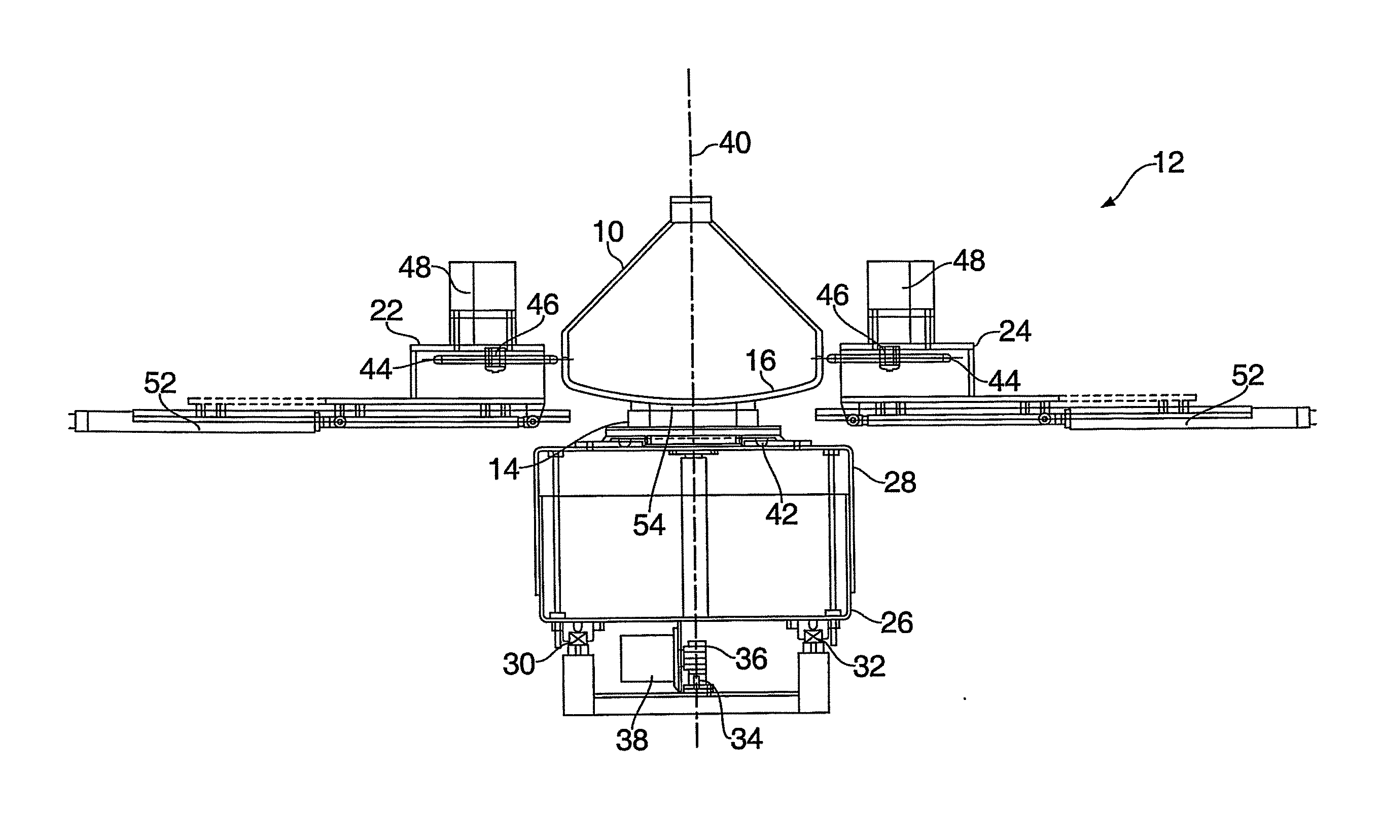
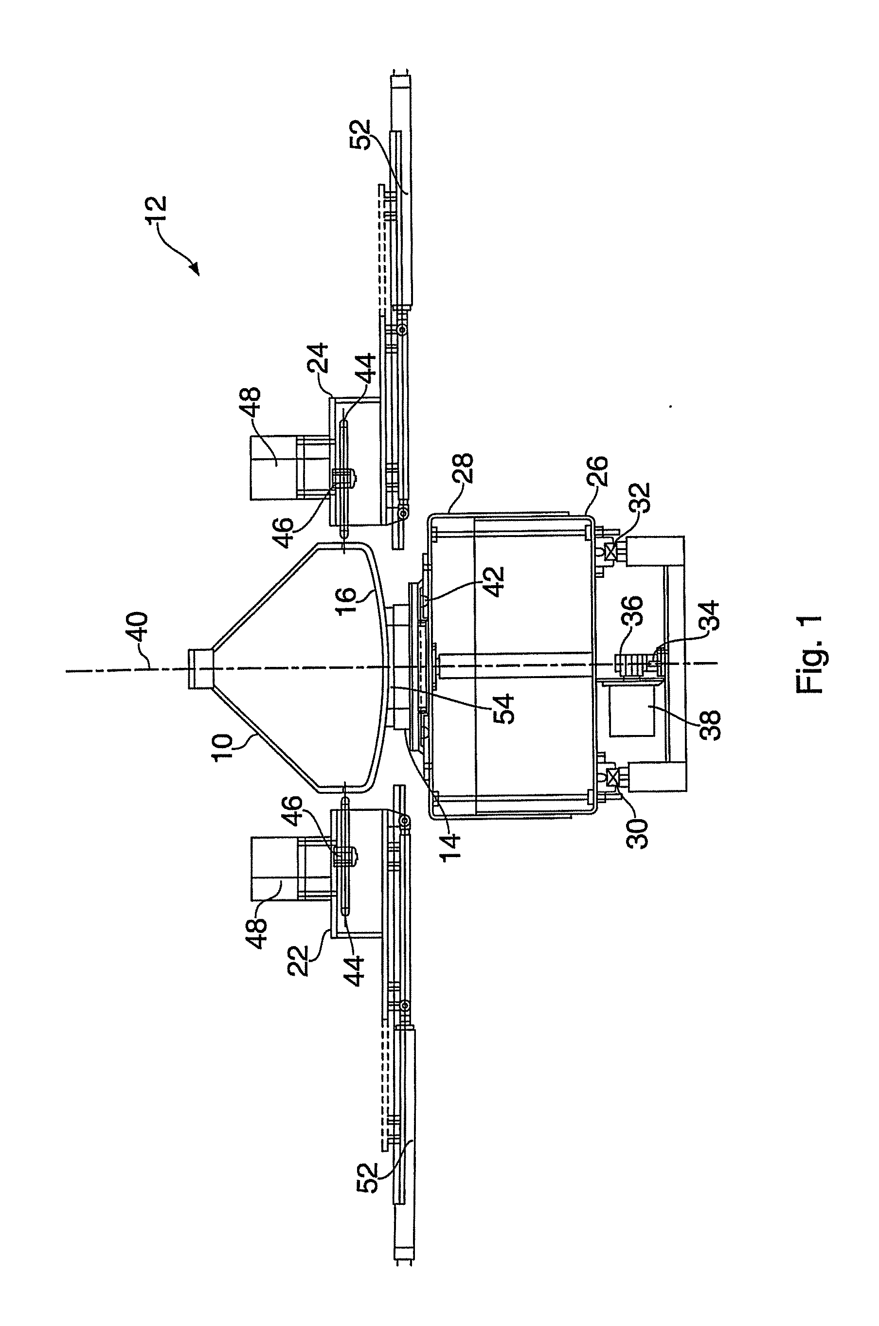
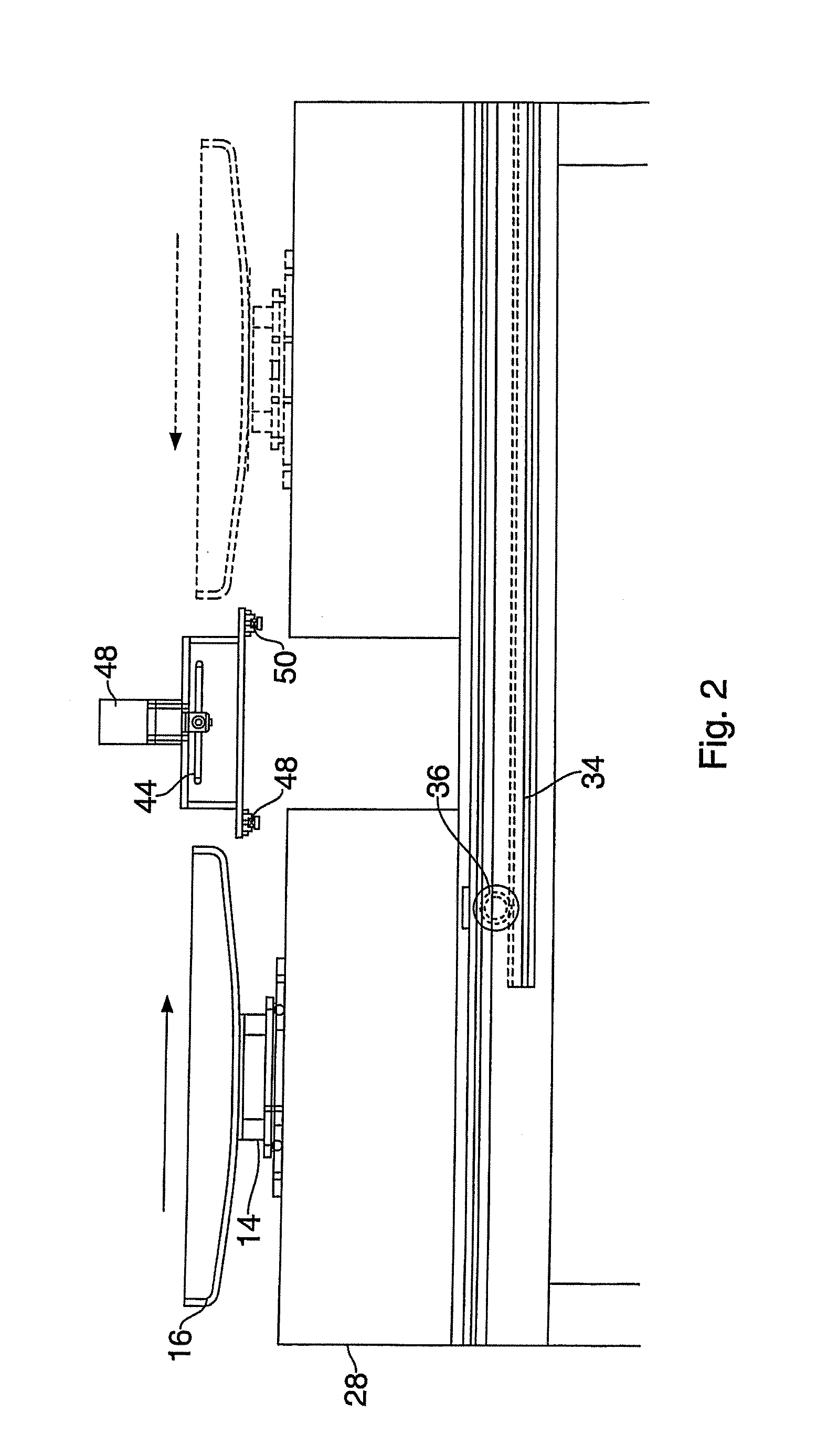
[0032]Referring firstly to FIG. 1, an apparatus for cutting a cathode ray tube 10 is indicated generally at 12. The apparatus 12 comprises a support means 14 for supporting the screen 16 of the cathode ray tube 10, first and second sensors 18,20 (shown in FIGS. 3 and 4) for determining the external dimensions of the screen 16, first and second spaced diamond cutting means 22,24, and displacement means 26 for moving the support means 14 relative to the diamond cutting means 22,24.

[0033]The displacement means 26 comprises a movable table 28 mounted on spaced parallel rails 30, 32. The table 28 is powered along the rails 30, 32 by means of a rack and pinion 34, 36. The rack 34 is rigidly fixed beneath the table 28, in alignment with and between the rails 30, 32. A motor 38 is slung beneath the table 28, which drives the pinion 36. The motor 38 is a variable speed hydraulic or electric motor.

[0034]The support means 14 and upper surface of the table 28 are vertically adjustable relative ...


PUM

PropertyMeasurementUnit
angleaaaaaaaaaa
displacementaaaaaaaaaa
speedaaaaaaaaaa

Abstract

An apparatus 12 for cutting a cathode ray tube 10 comprises a support means 14 for supporting the screen 16 of the cathode ray tube 10, first and second sensors 18,20 (shown in FIGS. 3 and 4) for determining the external dimensions of the screen 16, first and second spaced diamond cutting means 22,24, and displacement means 26 for moving the support means 14 relative to the diamond cutting means 22,24.

Description

[0001]The present invention relates to an apparatus and method for cutting a cathode ray tube, and in particular, to cutting a cathode ray tube (CRT) into two parts for the purpose of recycling of its component parts.BACKGROUND OF THE INVENTION[0002]CRTs are used, inter alia, in televisions, computer monitors and monitors for specialist applications, for example, in cash dispensers and industrial applications. In the UK alone, it is estimated that around 100,000 tonnes of CRTs are scrapped every year and require disposal. A CRT has a funnel section and a neck section, which are typically made from glass containing high levels of lead oxide. The funnel section is attached to a screen, which is typically made from glass containing high levels of barium oxide. The screen and funnel section are connected at a circumferential joint, known as a frit joint, which contains high levels of lead.[0003]Furthermore, the inside surface of the screen is coated with a fluorescent powder comprising ...

Claims


Application Information

Patent Timeline
Patent Type & Authority Applications(United States)
IPC IPC(8): B26D7/01B26D3/00B26D5/02B26D7/18C03B33/06H01J9/52
CPCC03B33/06H01J9/52B26D7/1863B26D7/01B26D5/20Y10T83/051Y10T83/536Y10T83/04Y10T83/207Y10T83/865Y10T83/541Y02W30/82
Inventor HARRIS, DAVID J.SEACROFT, NEIL R.
Owner CRT HEAVEN
Why Eureka
Try Eureka