Cutting device and method of glass substrate

A cutting device, glass substrate technology, applied in glass cutting devices, glass manufacturing equipment, fine work devices, etc., can solve the problems of scratches or pollution of glass surfaces and lines, environmental pollution of dust-free workshops, and impact on product quality, etc. , to avoid scratching the glass substrate circuit, reduce glass debris, and prolong the service life

Active Publication Date: 2012-06-27
SHENZHEN CHINA STAR OPTOELECTRONICS TECH CO LTD
View PDF2 Cites 20 Cited by
  • Summary
  • Abstract
  • Description
  • Claims
  • Application Information

AI Technical Summary

Problems solved by technology

Among them, the vertical crack 105 is a necessary condition for the subsequent slitting process, but the horizontal crack 104 does not need to be generated, and because of the generation of the horizontal crack 104, there will be redundant glass debris, and the glass debris will adhere to the surface of the glass substrate and the glass. On the circuit in the terminal area of ​​the substrate, the glass surface and the circuit will be scratched or p

Method used


Image

  • Cutting device and method of glass substrate
  • Cutting device and method of glass substrate
  • Cutting device and method of glass substrate

Examples


Embodiment Construction

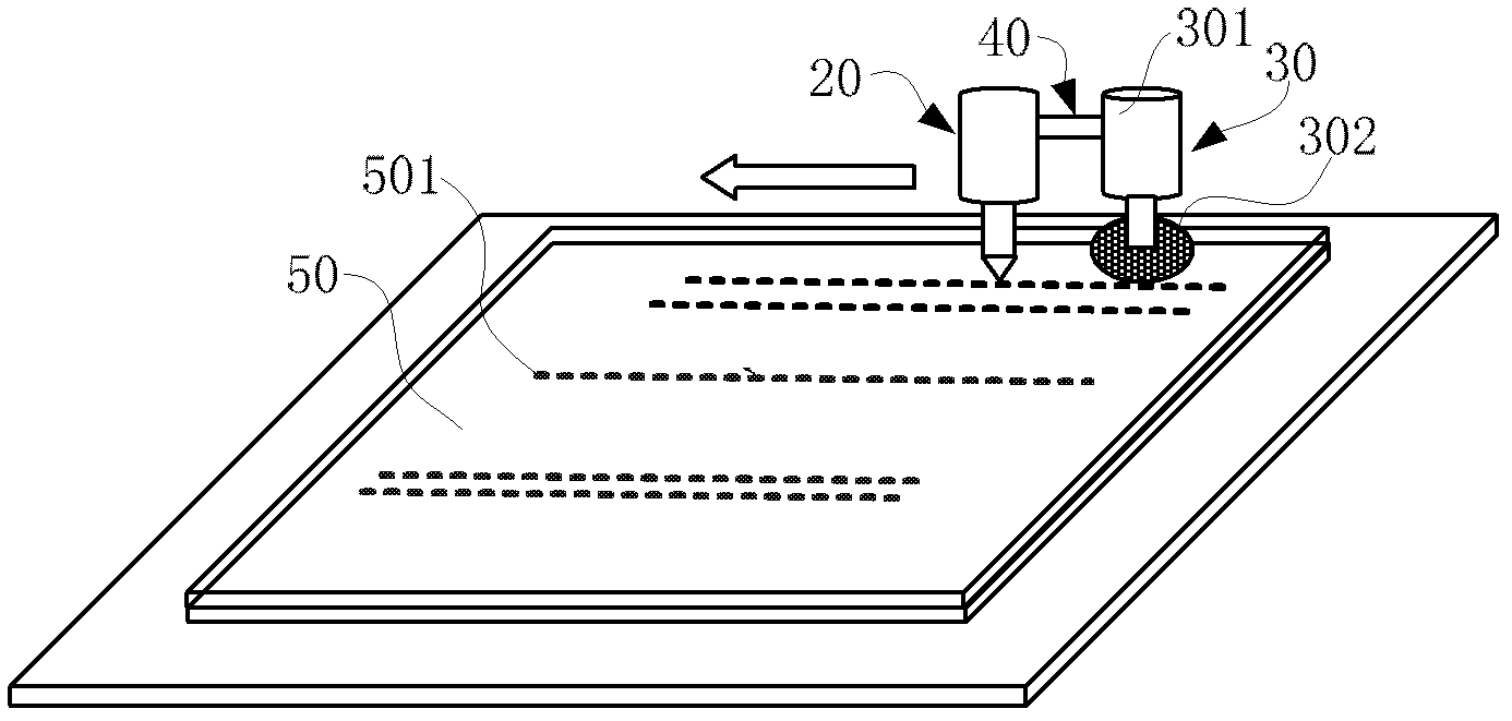
[0026] Please also refer to Figure 3 to Figure 5 , the glass substrate cutting device of the first embodiment of the present invention comprises a first laser emitting device 20, a first cutting device 30 and a connecting device 40, the first laser emitting device 20 and the first cutting device 30 are arranged oppositely along the cutting movement direction, connected The device 40 connects and holds the first laser emitting device 20 and the first cutting device 30, and the connecting device 40 can be fixed between the first laser emitting device 20 and the first cutting device 30, and can also be movably connected to hold the first laser emitting device 20 and the first cutting device 30. The laser emitting device 20 and the first cutting device 30, so that the relative positions of the first laser device 20 and the first cutting device 30 can be adjusted and corrected.

[0027] The first laser emitting device 20 may include a cooling device (not shown in the figure), and ...


PUM


Abstract

The present invention discloses a glass substrate cutting device, comprising a laser emission device and a cutting device, wherein the laser emission device emits a laser beam on the surface of a glass substrate to be cut to form a microgroove on the glass substrate surface, the cutting device is used for cutting the glass substrate at the position of the microgroove and comprises a cutting wheel fixing device and a diamond cutting wheel fixed on the cutting wheel fixing device. According to the invention, by using the laser emission device to emit the laser beam to form the microgroove on the glass substrate surface, the diamond cutting wheel can be embedded in the microgroove at the position of the microgroove to cut, thus the friction between the diamond cutting wheel and the glass substrate can be increased, the diamond cutting wheel is prevented from sliding when cutting, and the cutting precision is improved.

Description

technical field [0001] Embodiments of the present invention relate to the field of liquid crystal panels, and in particular to a glass substrate cutting device and method. Background technique [0002] At present, the main structure of TFT (Thin Film Transistor: Thin Film Transistor) liquid crystal display panel is an array substrate and a color filter substrate, and the liquid crystal is sandwiched between the two to form a box together. lines and pixel electrodes. The manufacturing process of the liquid crystal display panel mainly includes the array process of the array substrate and the color filter substrate, the box forming process of combining the array substrate and the color filter substrate and dropping the liquid crystal, and the subsequent module process. There are multiple units of liquid crystal display panels on the boxed glass substrate, and the multiple units of liquid crystal display panels are separated by cutting and splitting processes. [0003] For ex...

Claims


Application Information

Patent Timeline
IPC IPC(8): C03B33/02
CPCC03B33/076C03B33/02B28D5/00C03B33/0222C03B33/023
Inventor 庄益壮蔡荣茂廖学士文松贤邓明峰
Owner SHENZHEN CHINA STAR OPTOELECTRONICS TECH CO LTD
Why Eureka
Try Eureka