Shower apparatus

a technology of showering apparatus and shower head, which is applied in the direction of burners, combustion types, constructions, etc., can solve the problems of not providing the spraying of the shower with a voluminous feel and the concrete description of the properties of the bubbly water discharged, and achieve the effect of smooth production of bubbly water

Active Publication Date: 2011-08-18
TOTO LTD
View PDF8 Cites 12 Cited by
  • Summary
  • Abstract
  • Description
  • Claims
  • Application Information

AI Technical Summary

Benefits of technology

[0033]According to this preferred aspect, since the sheet-like stream of water is ejected radially from the throttle channel by being separated into fan-shaped portions, gaps are created, allowing air to pass therethrough. Therefore, air can travel between opposite sides of the sheet-like streams, and air can be supplied evenly to both sides of the sheet-like streams, contributing to smooth production of the bubbly water.
[0034]The present inve

Problems solved by technology

On the other hand, National Publication of International Patent Application No. 2006-509629 does not give any concrete description of properties of the bubbly water discharged from the shower apparatus described in the patent literature.
The above-de

Method used


Image

  • Shower apparatus
  • Shower apparatus
  • Shower apparatus

Examples


first embodiment

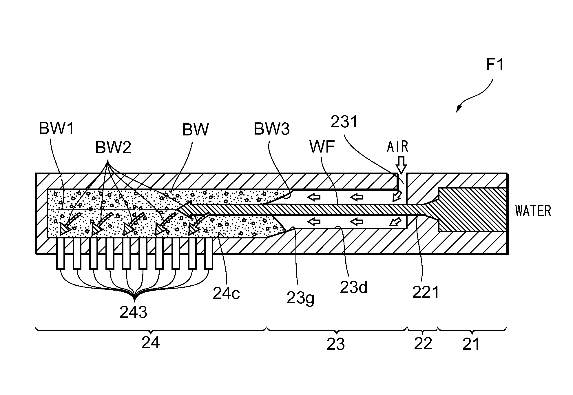
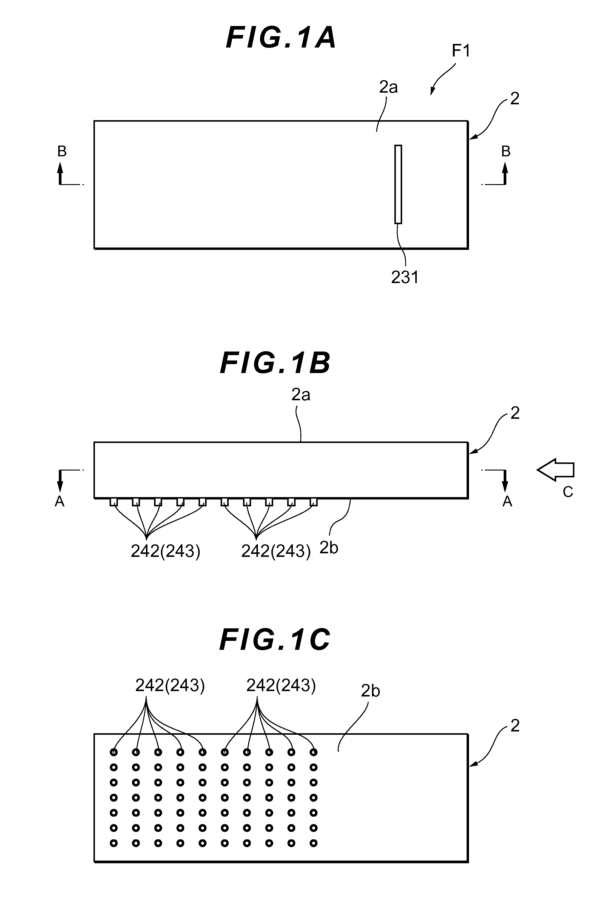
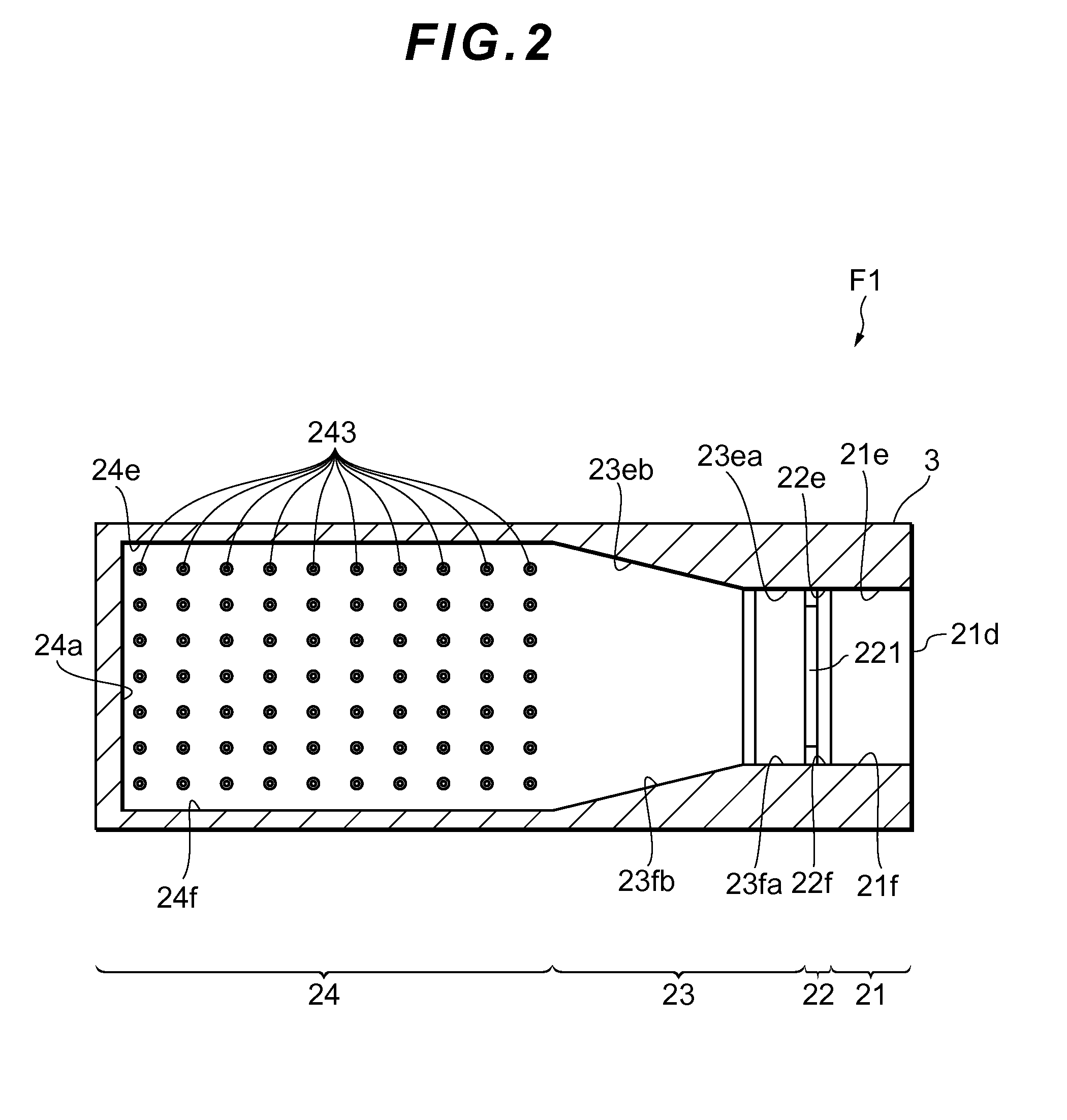
[0149]To achieve the operation and effect described above, the shower apparatus F1 according to the present invention includes, as described above, the water supply unit 21 adapted to supply water, the throttle unit 22 installed downstream of the water supply unit 21 and adapted to make the cross sectional area of the flow channel smaller than the water supply unit 21 and thereby eject passing water downstream, the aeration unit 23 installed downstream of the throttle unit 22 and provided with the opening 231 adapted to produce bubbly water by aerating the water ejected through the throttle unit 22, and the nozzle unit 24 installed downstream of the aeration unit 23 and provided with the plurality of nozzle holes 243 adapted to discharge the bubbly water BW by being formed along the ejection direction of the water ejected through the throttle unit 22.

[0150]The throttle unit 22 includes a single throttle channel 221 which is formed into a flat shape whose longer sides run along the d...

second embodiment

[0156]A shower apparatus which is a second embodiment of the present invention will be described with reference to FIG. 8. FIGS. 8(A) to 8(C) are diagrams showing a shower apparatus F3 according to the present invention, where FIG. 8(A) is a plan view, FIG. 8(B) is a side view, and FIG. 8(C) is a bottom view. As shown in FIG. 8(A), the shower apparatus F3 mainly includes a body 4 which is substantially disk-shaped and a water supply port 41d is formed in a top face 4a of the shower apparatus F3 (body 4).

[0157]As shown in FIG. 8(B), the body 4 of the shower apparatus F3 has its external shape formed by a cavity 4A in which the water supply port 41d is formed and a shower plate 4B in which nozzle holes 443 are formed. As shown in FIG. 8(C), a plurality of the nozzle holes 443 and an opening 431 are formed in a bottom face 4b of the body 4. According to the present embodiment, the nozzle holes 443 are arranged radially around the opening 431.

[0158]Next, the shower apparatus F3 will be ...


PUM


Abstract

Provided is a shower apparatus which can stably supply bubbly water through all nozzle holes and can cause water droplets of large, uniform size to land continuously on the user so as to allow the user to enjoy a shower with a voluminous feel as if the user were being showered by large drops of rain. The shower apparatus includes a water supply unit, a throttle unit adapted to eject passing water downstream, an aeration unit adapted to produce bubbly water by aerating the water ejected through the throttle unit, and a nozzle unit provided with a plurality of nozzle holes used to discharge the bubbly water, wherein the throttle unit has a flat-shaped throttle channel and water ejected through the throttle channel plunges into an air-liquid interface as a sheet-like stream, thereby producing bubbly water, which is then discharged through the nozzle hole.

Description

BACKGROUND OF THE INVENTION[0001]1. Field of the Invention[0002]The present invention relates to a shower apparatus.[0003]2. Description of the Related Art[0004]In the present technical field, a shower apparatus is known which discharges bubbly water by aerating water using a so-called ejector effect. Since the water flowing into the shower apparatus is distributed to multiple nozzle holes and sprayed therefrom, when the spray is aerated, the water flowing into the apparatus is aerated before being distributed among the nozzle holes.[0005]An example of such a shower apparatus is proposed in National Publication of International Patent Application No. 2006-509629. The shower apparatus described in National Publication of International Patent Application No. 2006-509629 comprises a plurality of nozzle holes provided in a front face of a disk-shaped housing shell and is configured to discharge water flowing in through the center of a rear face of the housing shell by distributing the w...

Claims


Application Information

Patent Timeline
IPC IPC(8): B05B7/32E03C1/084B05B1/14
CPCB05B7/0425B05B1/185
Inventor UKIGAI, KIYOTAKESATO, MINORUOHASHI, TAKAHIROAIHARA, YUTAKAOKAMOTO, MINAMINAGATA, KATSUYA
Owner TOTO LTD
Why Eureka
Try Eureka