Power conversion circuit and power conversion circuit system

a power conversion circuit and power conversion technology, applied in emergency power supply arrangements, transportation and packaging, anti-theft devices, etc., can solve the problems of low electric capacitance of dc-dc converter circuits, limited adaptable application range, and 1 does not disclose power conversion between two input/output ports

Active Publication Date: 2011-08-18
TOYOTA CENT RES & DEV LAB INC +1
View PDF4 Cites 119 Cited by
  • Summary
  • Abstract
  • Description
  • Claims
  • Application Information

AI Technical Summary

Benefits of technology

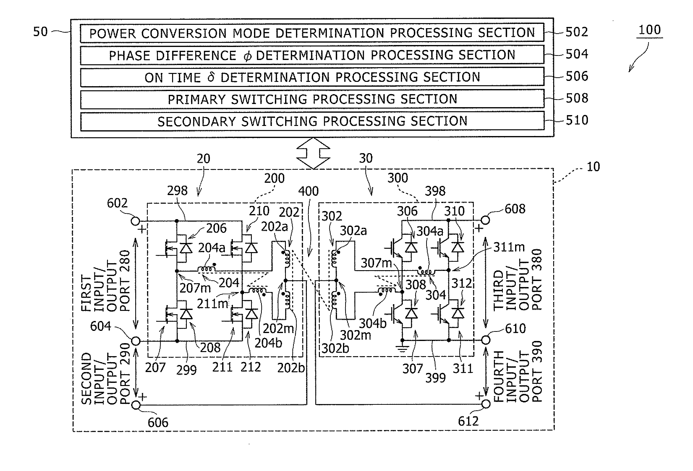
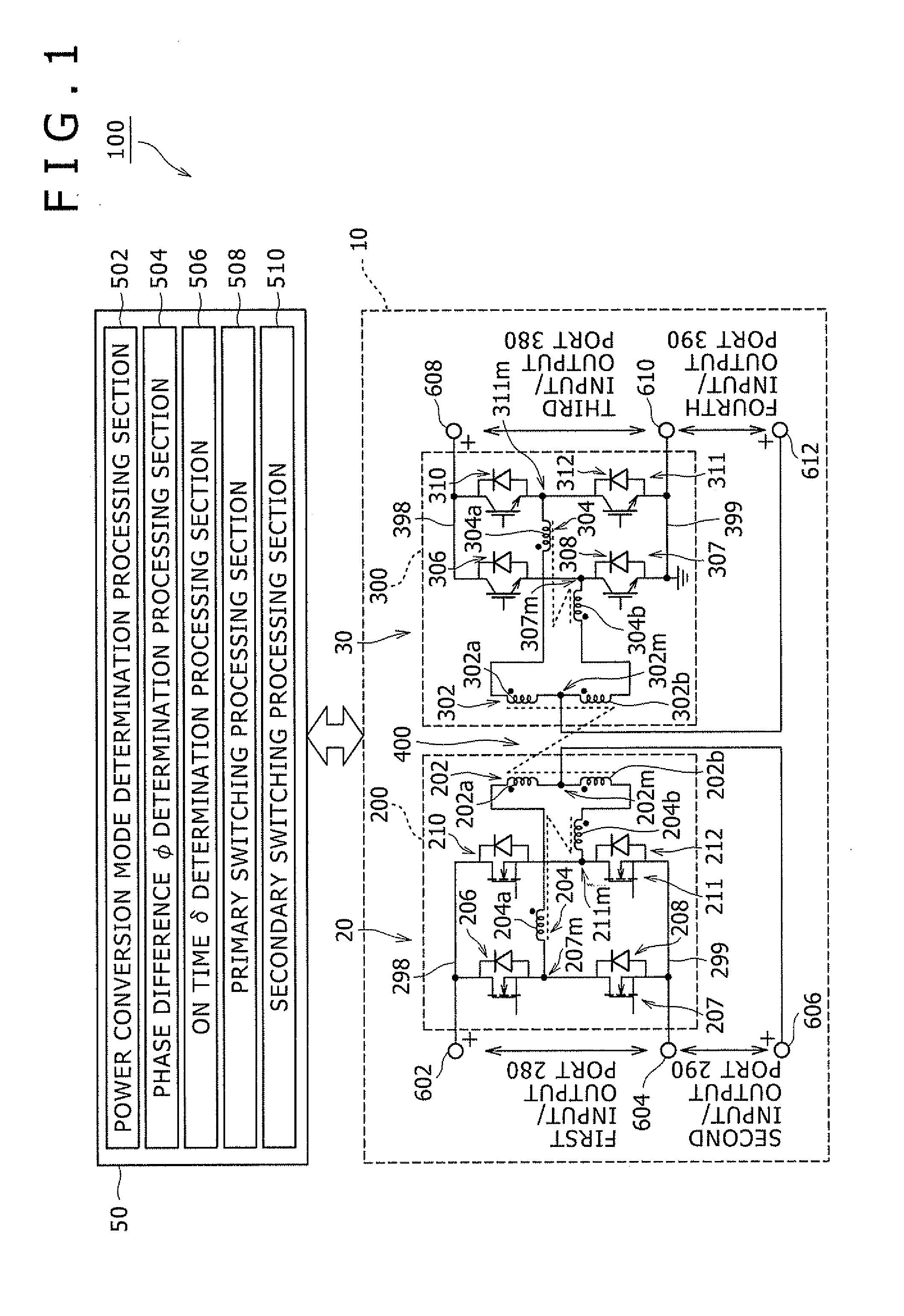
[0022]In addition, a power conversion circuit system according to the present invention comprises the above-described power conversion circuit, a secondary load connected to the third input/output port, a secondary power source connected to the fourth input/output port for supplying electric power to the secondary load, a primary capacitor connected to the first input/output port, a primary power source connected to the second input/output port for supplying electric power to the primary capacitor, and a control unit which performs control operation in such a manner that a stationary power component in required power of the secondary load is supplied from the secondary power source to the secondary load, while a sudden transient power component in the required power of the secondary load is supplied from the primary capacitor to the secondary load.
[0023]Further, a power conversion circuit system according to the present invention comprises the above-described power conversion circuit, a secondary load connected to the third input/output port, a secondary capacitor connected to the fourth input/output port, a first primary capacitive power source connected to the first input/output port, a second primary capacitive power source connected to the second input/output port, and a control unit which performs control operation in such a manner that a stationary power component in required power of the secondary load is supplied from the first primary capacitive power source to the secondary load, while a sudden transient power component in the required power of the secondary load is supplied from the secondary capacitor to the secondary load.
[0024]Further, a power conversion circuit system according to the present invention comprises the above-described power conversion circuit, a secondary load connected to the third input/output port, a first secondary capacitor connected to the third input/output port in parallel with the secondary load, a second secondary capacitor connected to the fourth input/output port, a primary load connected to the first input/output port, a primary capacitor connected to the first input/output port in parallel with the primary load, a primary power source connected to the second input/output port for supplying electric power to the primary load, and a control unit which performs control operation to transmit electric power between the primary conversion circuit and the secondary conversion circuit.
[0025]Still further, in the power conversion circuit system according to the present invention, the control unit preferably comprises a transmission controlling section which performs control operation to transmit electric power from the primary power source via the primary and secondary conversion circuits to the secondary load, a phase difference adjusting section which adjusts a phase difference between the primary conversion circuit and the secondary conversion circuit in light of feedback on transmission power from the primary power source to the secondary load to ensure that the transmission power from the primary source to the secondary load is maintained equal to predetermined power, a step-up controlling section which per...

Problems solved by technology

Although the above Patent Document 1 discloses that electric power is converted using the three input/output ports, the DC-DC converter circuit is low in electric capacitance, and limited in its range of adaptable application due to a configuration of u...

Method used


Image

  • Power conversion circuit and power conversion circuit system
  • Power conversion circuit and power conversion circuit system
  • Power conversion circuit and power conversion circuit system

Examples


Embodiment Construction

modification example of the power conversion circuit system according to the seventh example in the embodiment of the present invention;

[0047]FIG. 19 is a schematic diagram showing a specific configuration of the phase difference φ determination processing section in the second modification example of the power conversion circuit system according to the seventh example in the embodiment of the present invention;

[0048]FIG. 20 shows a third modification example of the power conversion circuit system according to the seventh example in the embodiment of the present invention;

[0049]FIG. 21 is a schematic diagram showing a specific configuration of the ON time δ determination processing section in the third modification example of the power conversion circuit system according to the seventh example in the embodiment of the present invention, and

[0050]FIG. 22 is a schematic diagram showing a specific configuration of the phase difference determination processing section in the third modif...


PUM


Abstract

A power conversion circuit system comprises a primary conversion circuit, a secondary conversion circuit, and a control circuit for controlling the primary and secondary conversion circuits. The primary conversion circuit comprises a primary full bridge circuit, which includes a bridge section composed of both a primary coil in a transformer and a primary magnetic coupling reactor in which two reactors are magnetically coupled, a first input/output port disposed between a positive bus bar and a negative bus bar of the primary full bridge circuit, and a second input/output port disposed between the negative bus bar of the primary full bridge circuit and a center tap of the primary coil in the transformer. The secondary conversion circuit has a configuration similar to that of the primary conversion circuit.

Description

PRIORITY INFORMATION[0001]This application claims priority to Japanese Patent Application Nos. 2010-031996 filed on Feb. 17, 2010 and 2010-275507 filed on Dec. 10, 2010, which are incorporated herein by reference in their entirety.BACKGROUND OF THE INVENTION[0002]1. Field of the Invention[0003]This invention relates to a power conversion circuit and a power conversion circuit system, and, more particularly, to a power conversion circuit having a plurality of input / output ports, and a power conversion circuit system including the power conversion circuit.[0004]2. Description of the Related Art[0005]It may be desired that, in a power conversion circuit having a plurality of input / output ports, electric power is converted between two input / output ports among the plurality of input / output ports. For example, Patent Document 1 (U.S. Pat. No. 7,408,794) discloses a DC-DC converter circuit which includes three input / output ports and a half bridge circuit. It is further disclosed that a hig...

Claims


Application Information

Patent Timeline
IPC IPC(8): H02J9/04H02M7/68
CPCB60R25/00H02J9/04H02M3/33592
Inventor ISHIGAKI, MASANORITOMURA, SHUJIUMENO, TAKAJIKIMURA, KENJI
Owner TOYOTA CENT RES & DEV LAB INC
Why Eureka
Try Eureka