Dc-to-dc converter

a converter and direct current technology, applied in the direction of dc-dc conversion, power conversion systems, instruments, etc., can solve the problems of difficult implementation of dc-to-dc converters b>100/b> in miniaturized electronic devices, large transformer tx, and low efficiency, etc., to achieve small size and high efficiency

Active Publication Date: 2011-08-18
SPI ELECTRONICS +1
View PDF6 Cites 1 Cited by
  • Summary
  • Abstract
  • Description
  • Claims
  • Application Information

AI Technical Summary

Benefits of technology

Accordingly, the present invention is directed to a direct current (DC)-t...

Problems solved by technology

However, since the DC-to-DC converter 100 simultaneously achieves the boost and the buck functions mainly through the transformer TX having the isolation function, the transformer TX has to burden all of the...

Method used


Image

  • Dc-to-dc converter
  • Dc-to-dc converter
  • Dc-to-dc converter

Examples


Embodiment Construction

The present invention will now be described more fully with reference to the accompanying drawings, in which exemplary embodiments of the invention are shown. Moreover, reference will now be made in detail to the present preferred embodiments of the invention, examples of which are illustrated in the accompanying drawings. Wherever possible, the same reference numbers are used in the drawings and the description to refer to the same or like parts.

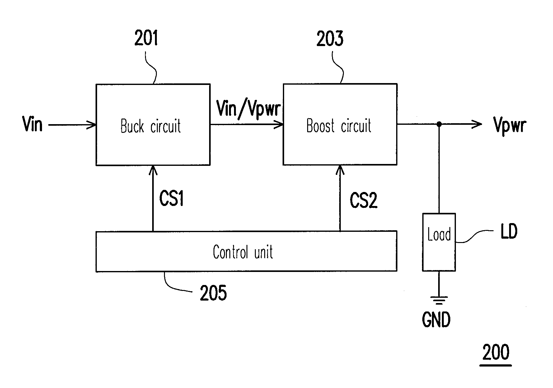
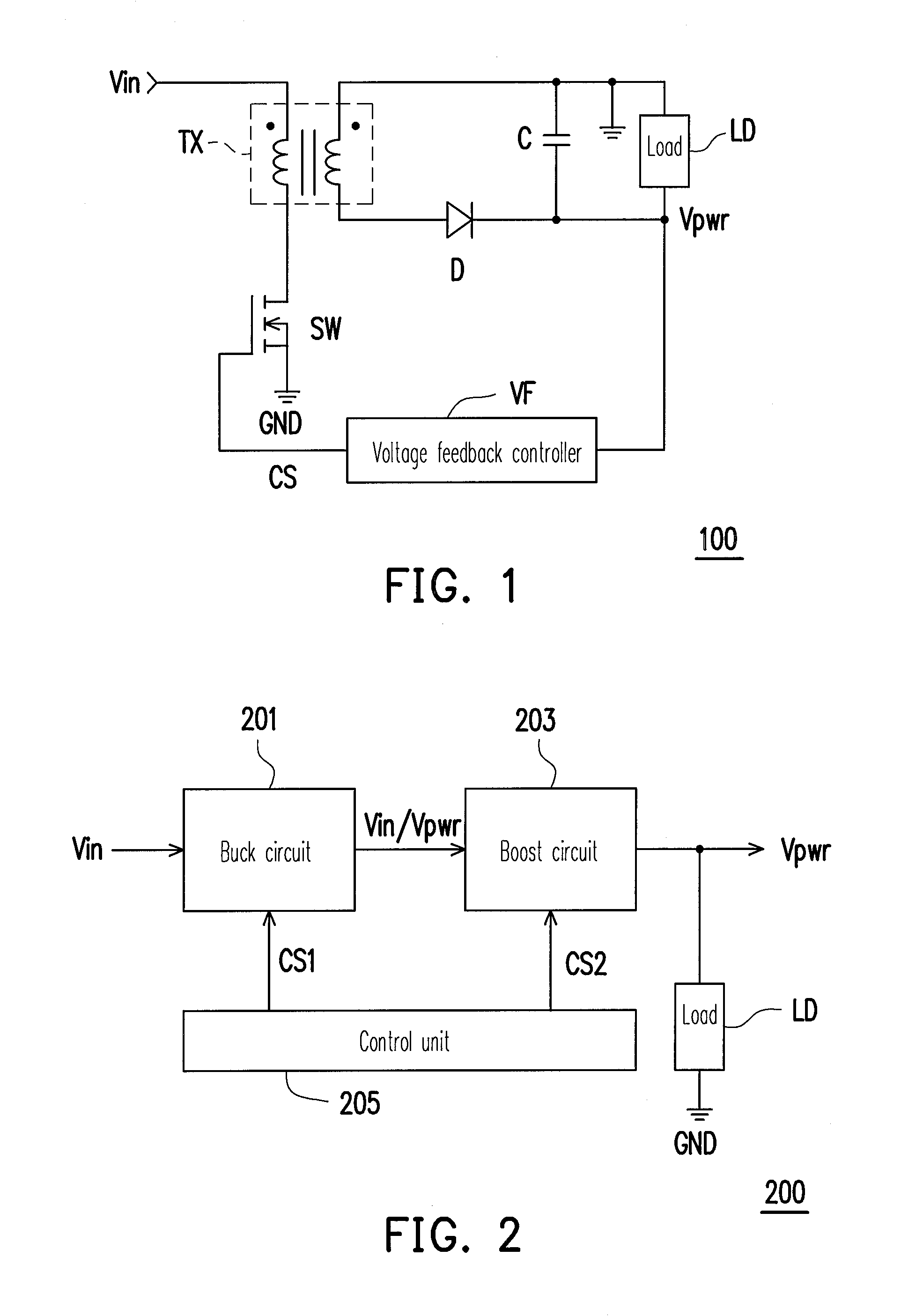
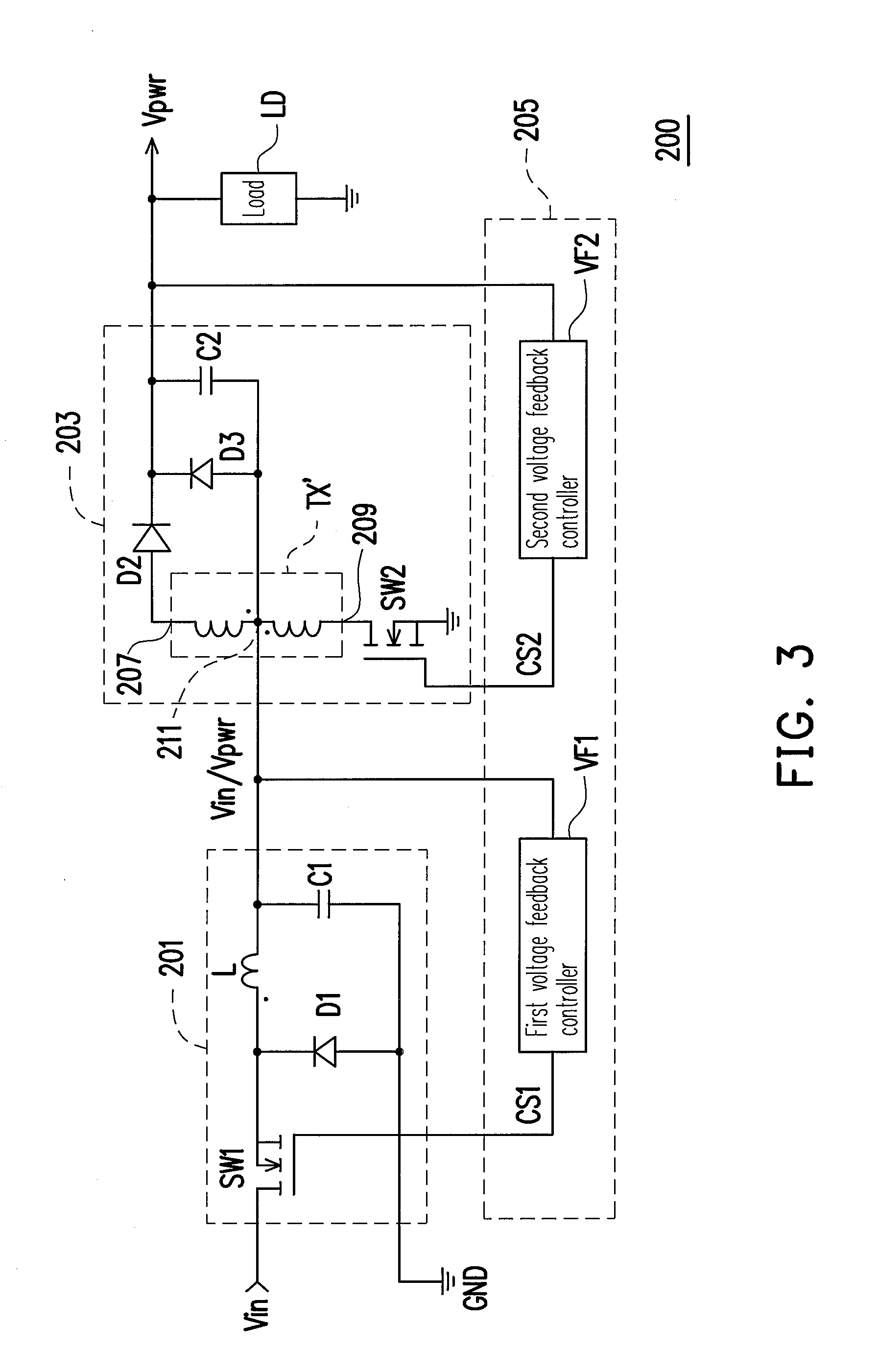
FIG. 2 is a block schematic diagram illustrating a direct current (DC)-to-DC converter 200 according to an embodiment of the present invention. Referring to FIG. 2, the DC-to-DC converter 200 is adapted for generating a power voltage Vpwr required by a load LD (for example, and electronic device, though the present invention is not limited thereto), and the DC-to-DC converter 200 includes a buck circuit 201, a boost circuit 203, and a control unit 205. In the present invention, an output power of the boost circuit 203 can be less than, grea...


PUM


Abstract

A DC-to-DC converter adapted for generating a power voltage required by a load and including a buck circuit and a boost circuit is provided. The buck circuit is used for receiving a DC input voltage, and outputting the power voltage by performing a buck process to the DC input voltage, or directly outputting the DC input voltage according to a first control signal. The boost circuit is used for receiving the power voltage or the DC input voltage both output from the buck circuit, and outputting the power voltage to the load by performing a boost process to the DC input voltage output from the buck circuit, or directly outputting the power voltage output from the buck circuit to the load according to a second control signal.

Description

CROSS-REFERENCE TO RELATED APPLICATIONThis application claims the priority benefit of Taiwan application serial no. 99104805, filed on Feb. 12, 2010. The entirety of the above-mentioned patent application is hereby incorporated by reference herein and made a part of this specification.BACKGROUND OF THE INVENTION1. Field of the InventionThe present invention relates to a power supply device, more particularly, to a direct current (DC)-to-DC converter having a boost / buck function and high efficiency.2. Description of Related ArtConventionally, to stably and accurately provide a power voltage required by a load (for example, an electronic device), a direct current (DC)-to-DC converter is generally designed to have a boost / buck function. FIG. 1 is a circuit schematic diagram illustrating a conventional DC-to-DC converter 100 having the boost / buck function. Referring to FIG. 1, the DC-to-DC converter 100 includes a transformer TX having an isolation function, a switch SW, a capacitor C, ...

Claims


Application Information

Patent Timeline
IPC IPC(8): G05F1/563
CPCH02M2001/007H02M3/158H02M1/007
Inventor TSAI, CHIH-CHANG
Owner SPI ELECTRONICS
Why Eureka
Try Eureka