
Laser guided parking apparatus and method

a technology of precisely guiding and parking apparatus, which is applied in the direction of traffic control systems, transportation and packaging, instruments, etc., can solve the problems of large devices, complex and antiquated, and inventions that do not combine simplicity, reliability, adjustability and compact design features, and achieve accurate and easy guiding of vehicles

Inactive Publication Date: 2011-08-18
BUTLER III GEORGE +1
View PDF2 Cites 12 Cited by
  • Summary
  • Abstract
  • Description
  • Claims
  • Application Information

AI Technical Summary

Benefits of technology

[0006]An object of the invention is to provide an apparatus and method for accurately and easily guiding a vehicle into a garage to a predetermined location.
[0007]A further object of the invention is to combine reliable ‘State-of-the-art’ compact diode laser technology with a mounting provision that is simple to install, adjust and utilize for parking a vehicle.
[0008]A further object of the invention is to provide an improved method for guiding a vehicle using highly visible linear lines which enable the driver to adjust the vehicle side to side and forward and rearward prior to stopping at a precise location.
[0010]The invention includes an apparatus and method and an article of manufacture for guiding a vehicle precisely into a predetermined parking location. More particularly the present invention relates to an apparatus composed of a currently available compact diode laser unit mounted to a holding device. The holding device (or holder) is designed to hold the laser unit. The holder fits into a base unit which in turn is mounted to the ceiling of the garage above the vehicle to be guided. The combination of laser, holder and base unit allows one to attach, adjust and focus the laser beams quickly, easily and accurately.
[0016]The line generating diode laser unit and mounting system provides the user the advantage of mounting the base with either a single screw and / or adhesive tape. The laser holder mounts to the base by way of a fully articulating, (pivot and rotating) ball and socket design. Furthermore, the laser lines can be adjusted and focused to provide the best sharpness by turning the laser tip ring. Once the focus is set, the linear ‘X’ (or ‘cross’) pattern can be rotated (clocked) and positioned using the holder ‘rotation wheel’ and ‘ball and socket’ pivoting mechanisms.

Problems solved by technology

This device is large, complex and antiquated.
In general these inventions do not combine simplicity, reliability, adjustability and compact design features along with the ability to project highly visible linear lines to accurately guide and position a vehicle to a pre-described location inside a garage or other similar structure.
In addition, none of these inventions include a ‘target’ appliqué for use in aligning a vehicle.

Method used


Image

  • Laser guided parking apparatus and method
  • Laser guided parking apparatus and method
  • Laser guided parking apparatus and method

Examples


Embodiment Construction

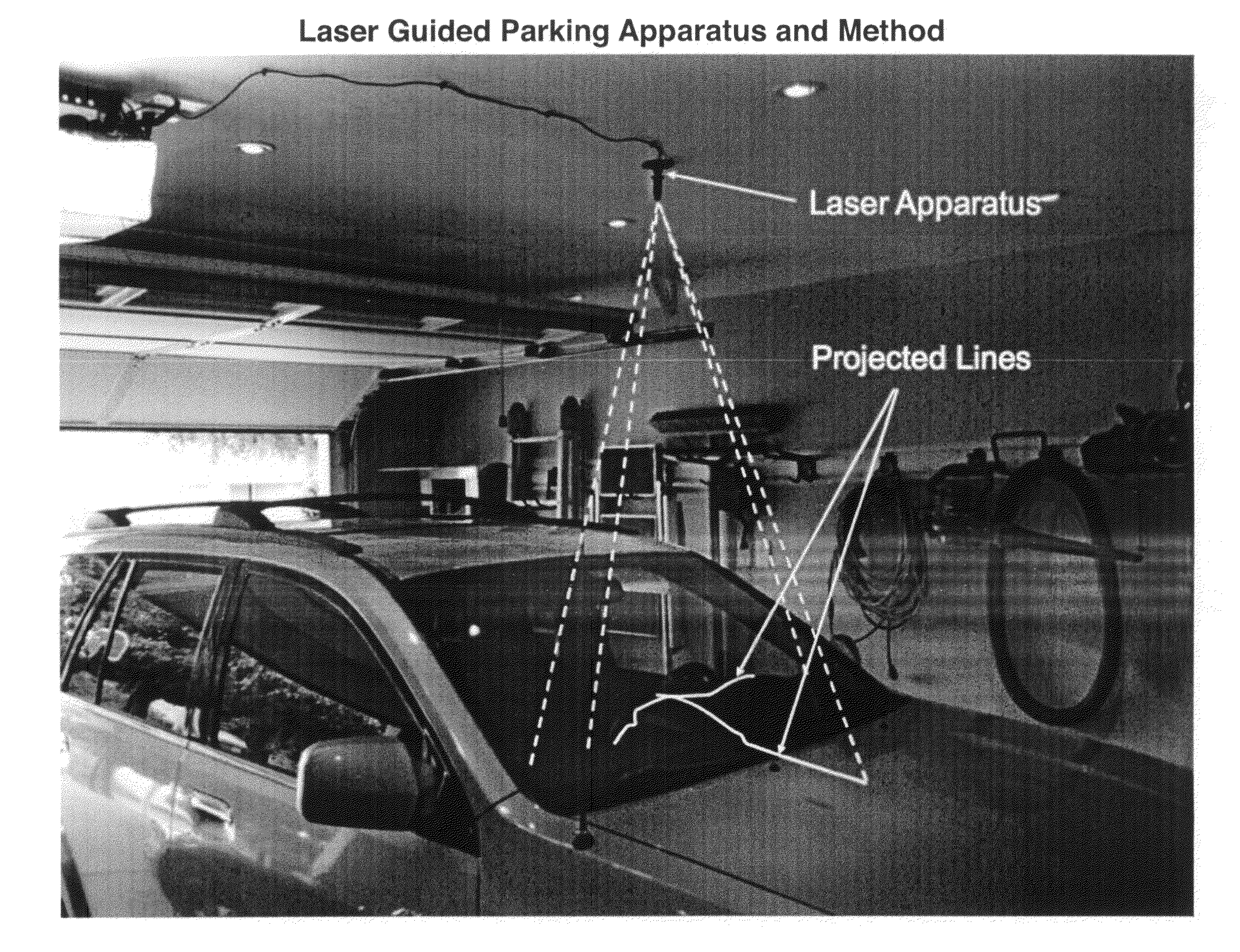
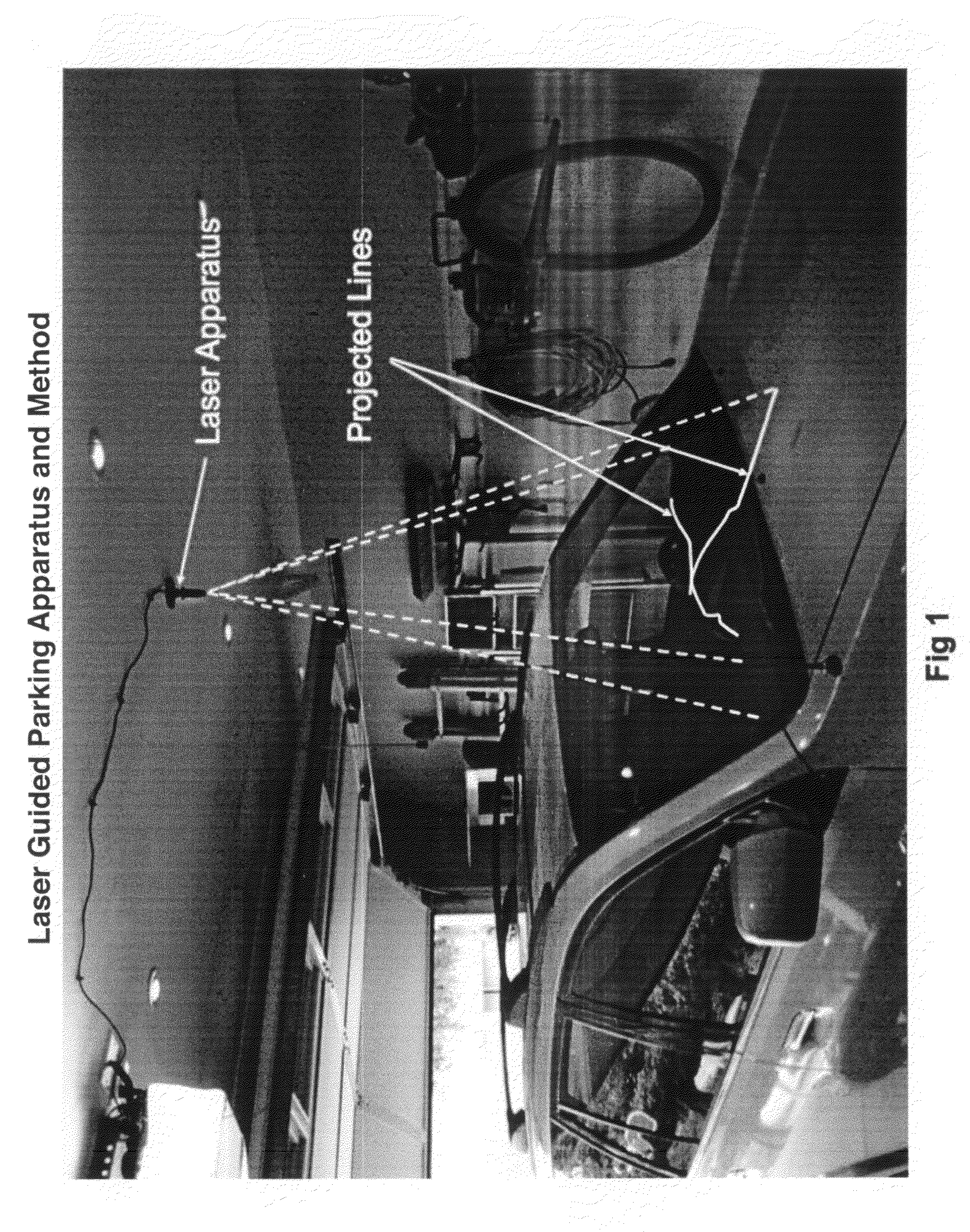
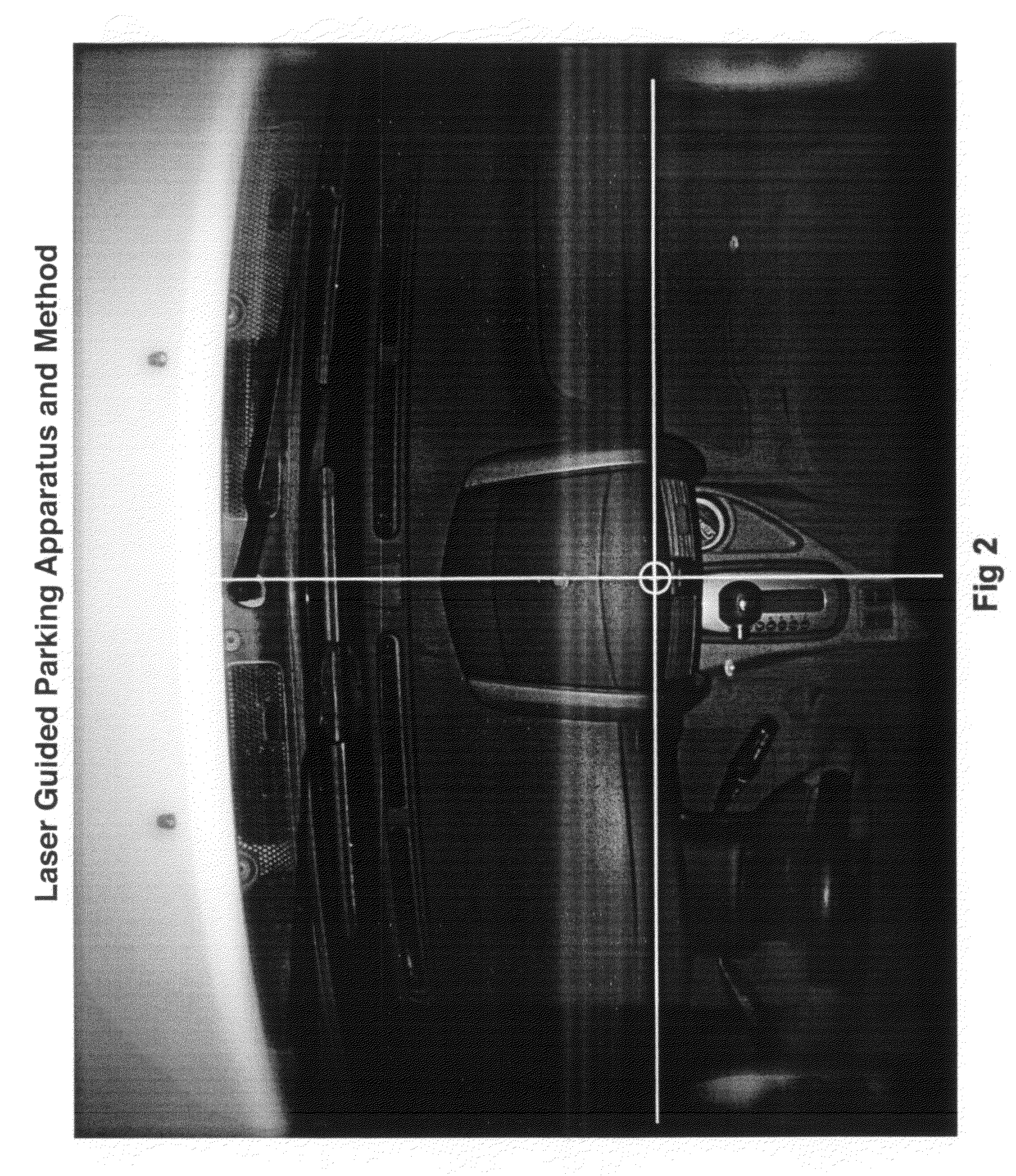
[0028]As shown in FIGS. 1 through 3 are the illustrative views depicting the linear lines projected from the compact laser apparatus.

[0029]As shown in FIGS. 4 through 6 is the preferred embodiment of the precision parking apparatus composed of a compact diode laser 1, a plastic holder with rotation wheel 2, a plastic base 3. Also shown are methods for attachment of the laser apparatus to a garage ceiling or similar structure (above the vehicle) using an adhesive double-sided tape 4, and or a screw 5.

[0030]As shown in FIG. 7 is the preferred embodiment of the various laser line patterns that can be projected by the compact diode laser.

[0031]As shown in FIG. 8 is the preferred embodiment of the various target designs that is used for aligning the laser ‘cross’ lines to a prescribed location on the dashboard or other similar location on the vehicle. These targets can be printed onto an adhesive backed appliqué material. Note that it is not necessary to have a ‘target’ appliqué but rath...


PUM


Abstract

This abstract describes an apparatus and method for accurately parking a vehicle within an enclosed space such as a garage. The apparatus uses a compact diode laser and is mounted directly to a ceiling or to a device mounted to the ceiling such as a garage door opener unit. When mounted above the vehicle the bright red laser lines are projected from the laser downward and aligned onto a specific surface for the driver to see such as the top surface of a vehicle dashboard. These lines intersect each other forming an ‘X’ (or ‘cross’). This ‘X’ can be aligned with either an existing dashboard feature or with a ‘target’ which is adhered to the dashboard. When a vehicle enters into a garage the first projected laser line that the driver will see will be the longitudinal line. The longitudinal line enables the driver to adjust the vehicle to the right or left as the vehicle continues into the garage. The second projected laser line appears laterally as the driver pulls forward to a stop. When this lateral line and longitudinal line align with the target or other specific location on the dashboard, the driver stops the vehicle. At this point the driver has positioned his vehicle exactly where he wants it to be within the garage.

Description

CROSS REFERENCE TO RELATED APPLICATIONS[0001]Application no. 61303696, ‘Laser Guided Parking Apparatus and Method’ Dated: 12 Feb. 2010, Inventor: George H. Butler IIIFIELD OF THE INVENTION[0002]The invention relates to an apparatus and method for precisely guiding a vehicle into a preselected parking location. More particularly, the present invention relates to an apparatus which projects a combination of bright laser lines to act as alignment guides for accurately positioning a vehicle inside a garage or other similar area.BACKGROUND OF THE INVENTION[0003]The prior art includes numerous devices and methods for guiding a vehicle into an enclosed area such as a garage. Devices using infrared beams, laser dots, laser lines, ultrasonic beams, direct contact switches, microwave beams, etc. The following patents which are each incorporated herein reference, disclose such arrangements:[0004]U.S. Pat. No. 5,285,072 issued to B. White; U.S. Pat. No. 5,878,072 issued to M. Greisz; U.S. Pat. ...

Claims


Application Information

Patent Timeline
IPC IPC(8): B60Q1/48
CPCE04H6/426
Inventor BUTLER, III, GEORGESTAGGERS, SCOTT L.
Owner BUTLER III GEORGE
Learn More