Screen unit

a technology of screen unit and screen, which is applied in the field of screen unit, can solve the problems of deformation of images, difficult to maintain the vertical posture and the force on the front surface side of the elevating mechanism is not balanced against the force on the rear surface side,

Active Publication Date: 2011-08-18
SEIKO EPSON CORP
View PDF7 Cites 13 Cited by
  • Summary
  • Abstract
  • Description
  • Claims
  • Application Information

AI Technical Summary

Benefits of technology

[0010]An advantage of some aspects of the invention is to provide a technology capable of solving at least a part of the problems described above and the invention can be implemented as the following forms.

Problems solved by technology

Thus, the force on the front surface side of the elevating mechanism is not balanced against the force on the rear surface side.
In this case, the elevating mechanism is difficult to be maintained in a vertical posture, and inclined toward the side to which the screen member is attached.
As a result, the screen member itself is inclined, causing deformation of images projected thereon from a projector.
In this case, the screen itself attached to the front surface side of the connecting mechanism is inclined, causing deformation of images projected on the projection surface of the screen from a projector or the like.
Thus, a hand or the like cannot be easily inserted into the joint of the elevating mechanism, which reduces the possibility of unexpected danger to a finger, a nail or the like.

Method used


Image

  • Screen unit
  • Screen unit
  • Screen unit

Examples


first embodiment

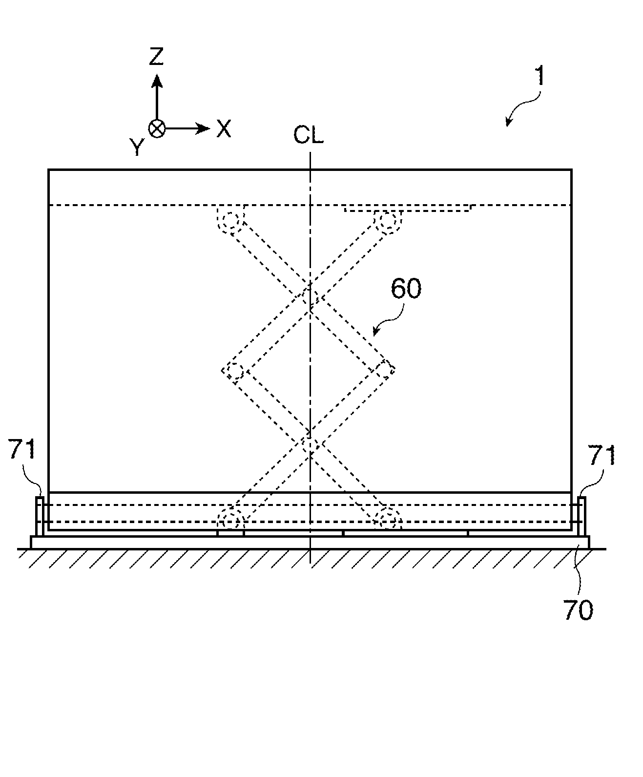
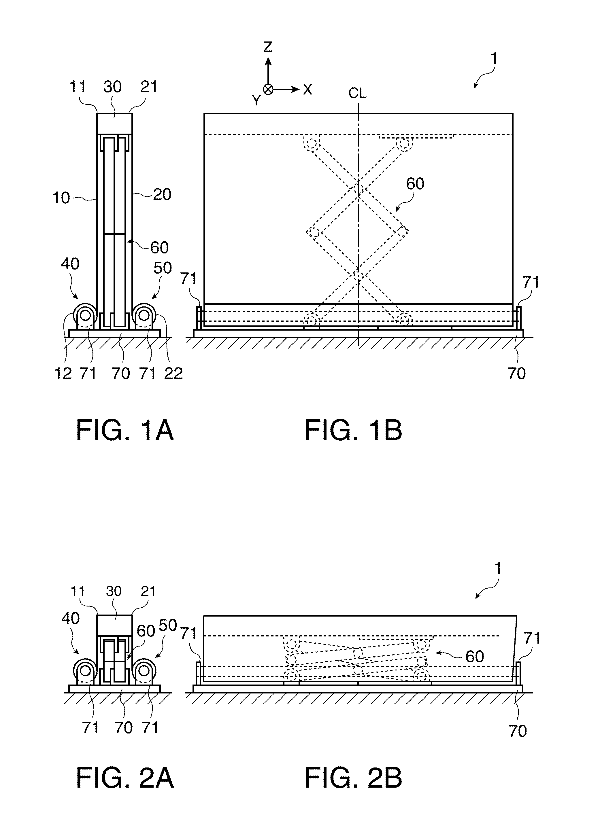
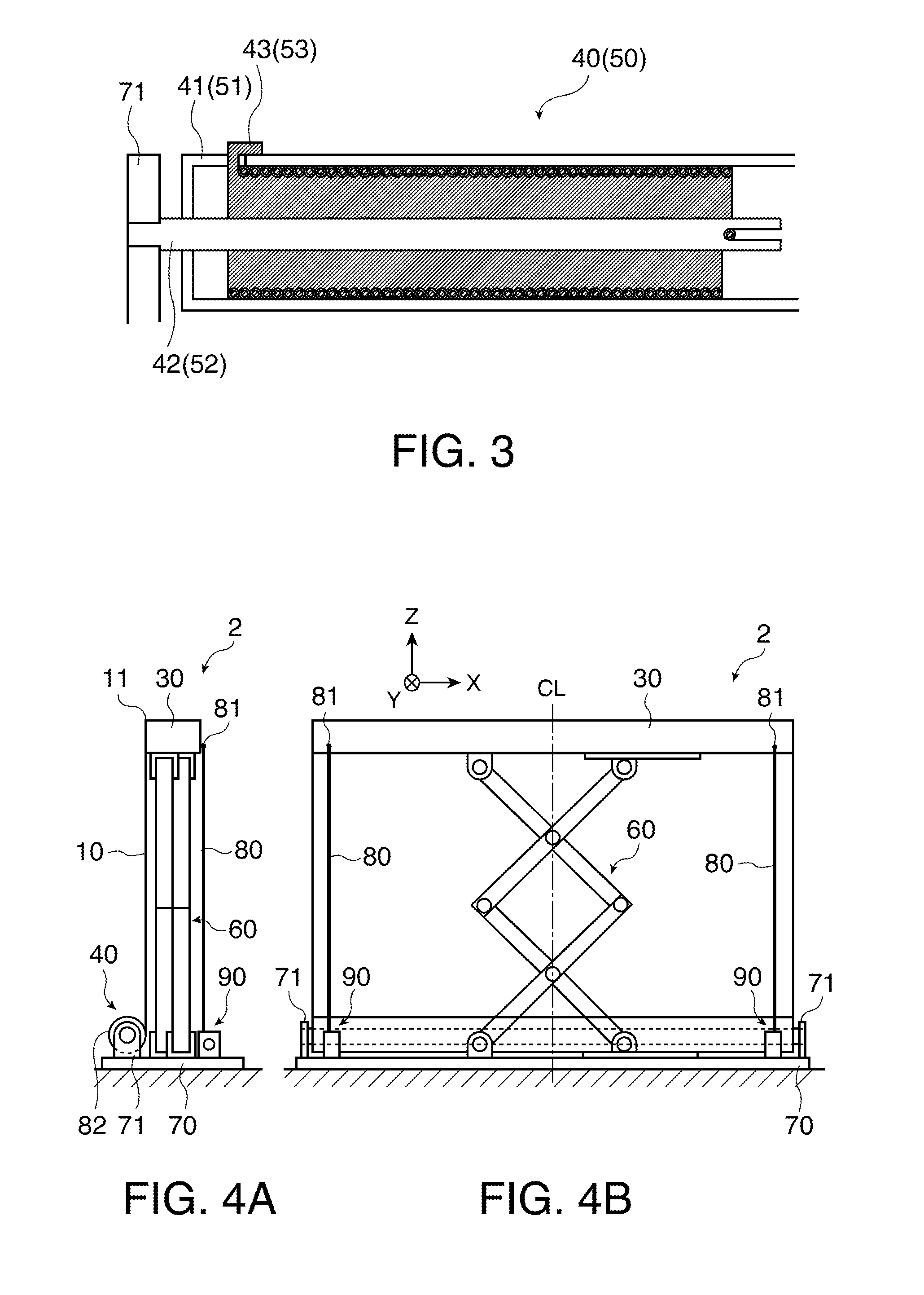
[0057]A screen unit according to a first embodiment is now described with reference to FIGS. 1A and 1B, 2A and 2B, and 3. FIGS. 1A and 1B, 2A and 2B, and 3 illustrate the general structure of the screen unit according to the first embodiment. FIGS. 1A and 1B show the screen unit in an expanded condition. FIG. 1A is a side view of the screen unit, while FIG. 1B is a rearview of the screen unit. FIGS. 2A and 2B show the screen unit in a stored condition. FIG. 2A is a side view of the screen unit, while FIG. 2B is a rear view of the screen unit. FIG. 3 illustrates the details of a winding structure in this embodiment.

[0058]As illustrated in FIGS. 1A and 1B, a screen unit 1 in the first embodiment includes a screen 10 as a substantially rectangular screen member having flexibility, a supplementary curtain 20 formed by flexible material as a tensioning member, a support member 30 as a first support member (support body), a winding mechanism 40 as a second support member (support body), a...

second embodiment

[0073]A screen unit according to a second embodiment is now described with reference to the drawings. FIGS. 4A and 4B, 5A and 5B, and 6 illustrate the general structure of the screen unit in the second embodiment. More specifically, FIGS. 4A and 4B show the screen unit in the expanded condition. FIG. 4A is a side view of the screen unit, and FIG. 4B is a rear view of the screen unit. FIGS. 5A and 5B show the screen unit in the stored condition. FIG. 5A is a side view, and FIG. 5B is a rear view. FIG. 6 illustrates the detailed structure of a winding mechanism according to this embodiment.

[0074]A screen unit 2 in the second embodiment has a structure same as that of the screen unit 1 in the first embodiment except that wires 80 as flexible string-shaped members corresponding to tensioning members and winding structures 90 as third support members are provided. The same reference numbers are given to parts and elements same as the corresponding parts and elements in the first embodime...

third embodiment

[0085]A screen unit according to a third embodiment is now described with reference to FIGS. 7A and 7B, 8A and 8B, and 9A and 9B. FIGS. 7A and 7B, 8A and 8B, and 9A and 9B illustrate the general structure of the screen unit in the third embodiment. More specifically, FIG. 7A is a side view of the screen unit in the expanded condition, and FIG. 7B is a rear view of the screen unit in the expanded condition. FIG. 8A is a plan view of a screen section, and FIG. 8B is a cross-sectional view of a winding mechanism. FIG. 8A shows a condition of the screen section removed from the screen unit and expanded. FIG. 9A is a side view of the screen unit in the stored condition, and FIG. 9B is a rearview of the screen unit in the stored condition.

[0086]As illustrated in FIGS. 7A and 7B, a screen unit 201 in the third embodiment includes a screen section 210, a base member 220, a winding shaft 240 as a second support member (support body), a winding shaft 242 as a third support member (support bod...


PUM


Abstract

A screen unit includes: a screen member; a first support member which supports one end of the screen member; a second support member which supports the other end of the screen member; a stretching and contracting device which expands the screen member; and a tensioning member disposed on the side opposite to the side where the screen member is provided with respect to the stretching and contracting device to apply tension in a direction substantially parallel with the direction from the first support member to the second support member.

Description

[0001]The entire disclosure of Japanese Patent Application Nos. 2010-33251, filed Feb. 18, 2010 and 2010-110885, filed May 13, 2010 are expressly incorporated by reference herein.BACKGROUND 1. Technical Field[0002]The present invention relates to a screen unit. 2. Related Art[0003]A screen unit which includes a substantially rectangular screen member having flexibility, a winding shaft for supporting one end of the screen member and functioning as a shaft around which the screen member is wound, a support body for supporting the side of the screen member opposed to the side supported by the winding shaft, and an elevating mechanism attached to the support body to control the height of the screen member is known (for example, see JP-A-2000-131766).[0004]In addition, a screen unit which includes a screen, an upper end support member for supporting one end of the screen, a base member to which a winding member is attached, the winding member for supporting the other end of the screen w...

Claims


Application Information

Patent Timeline
Patent Type & Authority Applications(United States)
IPC IPC(8): G03B21/58G03B21/56
CPCG03B21/58
Inventor KUROI, KIYOSHI
Owner SEIKO EPSON CORP
Why Eureka
Try Eureka