Fluidics-balanced fluid bearing

a fluid bearing and fluid technology, applied in the direction of bearings, shafts and bearings, shafts, etc., can solve the problems of unsuitable high-speed and high-pressure machinery, load requires a high degree of flexibility and rapid response time, and rotary machinery of the prior art typically lacks this flexibility. , to achieve the effect of fast response time, high flexibility and fast response tim

Inactive Publication Date: 2006-03-07
AEROJET GENERAL CORP
View PDF27 Cites 3 Cited by
  • Summary
  • Abstract
  • Description
  • Claims
  • Application Information

AI Technical Summary

Benefits of technology

[0008]It has now been discovered that the forces on the rotor in high-speed rotary machinery can be balanced with a fast response time and high flexibility by a fluid bearing that supplies fluid flow or pressure to selected sites in the gap between the rotor and the stator as a fluidic response to load signals generated by the machinery itself. This self-balancing bearing is capable of use as either a hydrodynamic and hydrostatic bearing and offers the fast response times (approximately 0.005 msec or less) that are typical of fluidics devices in general. The balancing forces generated in accordance with this invention can be used for balancing a thrust load on the rotor, a radial load, or both. The fluidics force transmission is achieved by one or more channels joining the gap with a source of pressurized fluid in conjunction with a fluid flow regulator that controls either the flow of fluid into, or the pressure of fluid in, the channel. The fluid pressure is allowed to increase until the control loop indicates that clearance between the rotor and stator that had been reduced by the load force has been restored and the rotor has been stabilized in a low-friction position. The signal generated in the control loop may itself be a fluidics signal or any other signal that is capable of serving as an indication of pressure or a pressure change or differential. Examples of signals other than fluidics signals are electrical signals and pneumatic signals.
[0010]Among the various advantages offered by this invention are the ability to change the fluidic components by simple disassembly of the rotor and stator, without requiring additional machining of the pump housing or rotor. In embodiments in which the fluidics components are controlled electronically, closed-loop features can be used that are readily changed without changing the fluidics components or disassembling the rotor and stator. Systems in accordance with this invention can also be driven by a mechanical pilot stage with fluidic components that provide a high level of control and a control loop whose gain can be set electronically.

Problems solved by technology

The average consumer may be most familiar with rolling element bearings, but these are unsuitable for high-speed and high-pressure machinery due to the speed and load capacity limitations of a typical rolling element bearing and the wear that such a bearing suffers during extended use.
Transient loads present a special challenge to the design of the bearing, since balancing these loads requires a high degree of flexibility and rapid response time.
Rotary machinery of the prior art typically lacks this flexibility.

Method used


Image

  • Fluidics-balanced fluid bearing
  • Fluidics-balanced fluid bearing
  • Fluidics-balanced fluid bearing

Examples


Embodiment Construction

[0018]The novel concepts of this invention are susceptible to a variety of ways of implementation and a wide range of constructions, encompassing rotary machinery in general, whether for manufacturing uses, consumer uses, or transportation such as aircraft motors and engines. An understanding of the invention as it applies to all such embodiments is best attained by a detailed review of one form of implementation. The following description and the attached drawings are addressed to one such implementation.

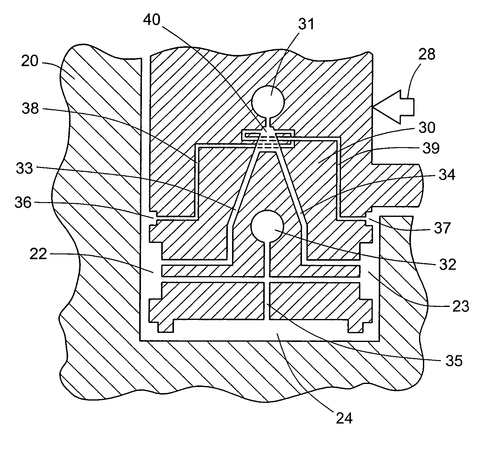
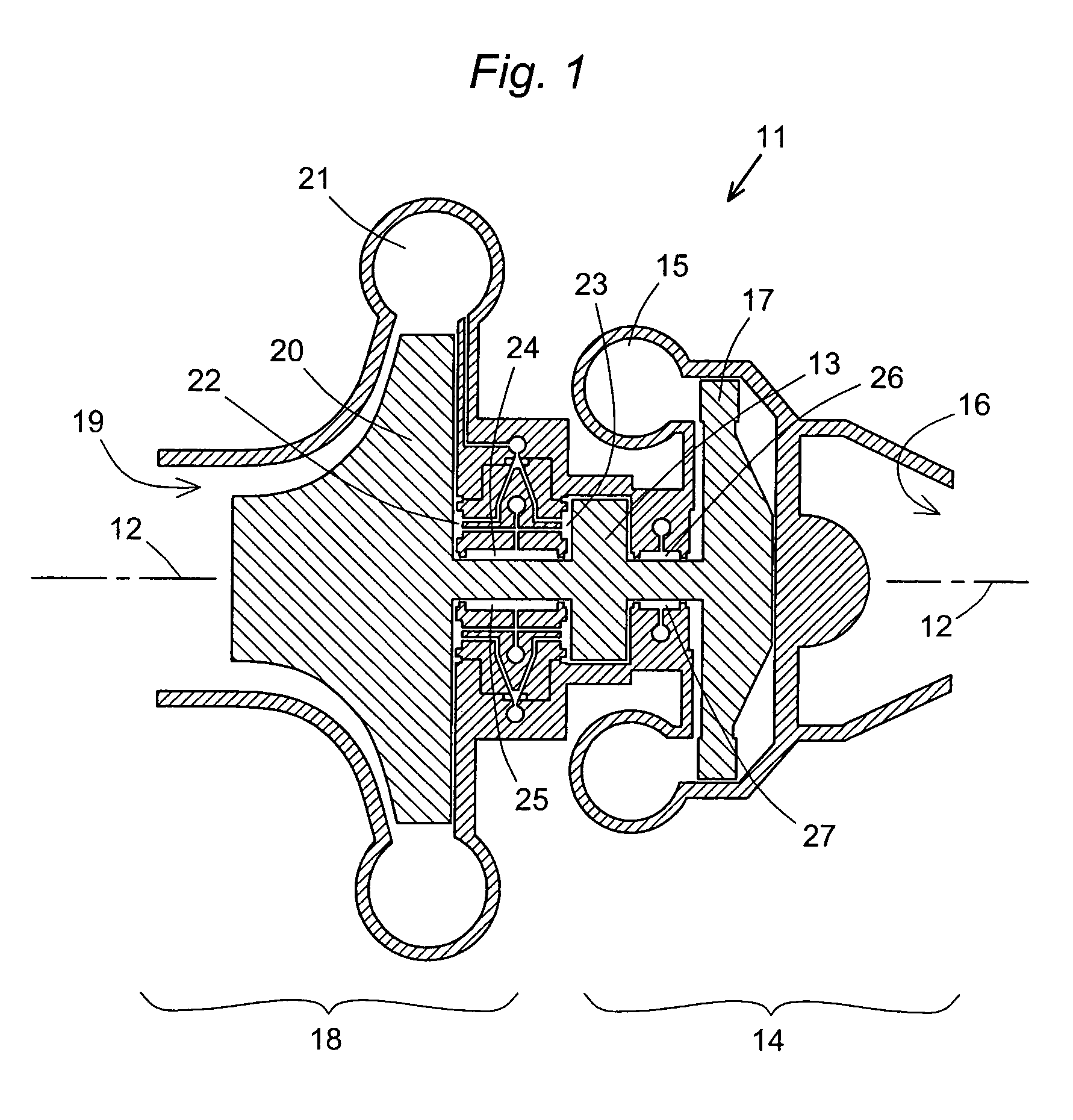
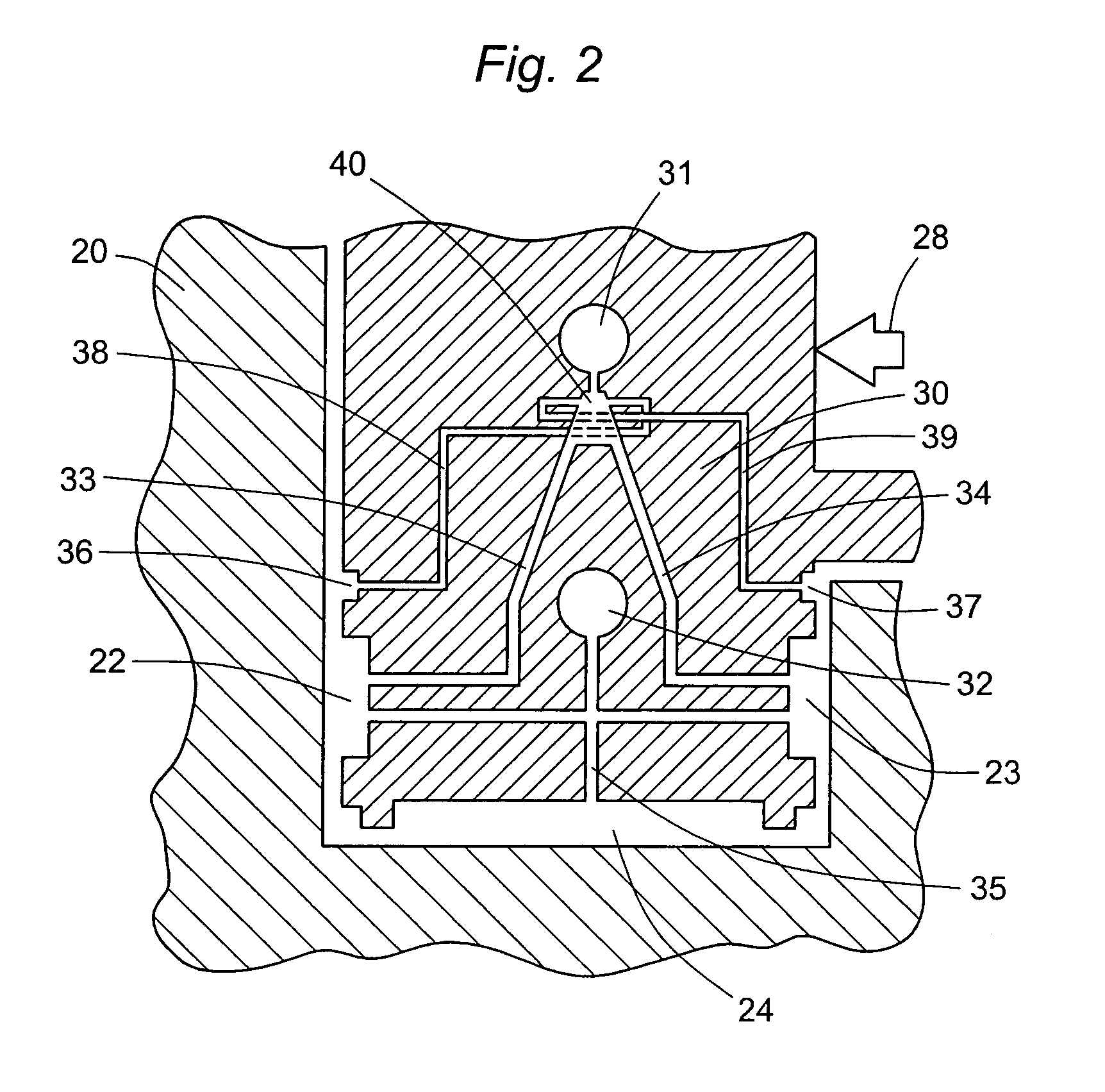
[0019]FIG. 1 is a cross section of a turbopump 11 that contains features embodying the present invention. This turbopump, which is designed for use in a rocket engine, is a body of revolution about an axis 12, which is also the axis of rotation of the turbopump rotor 13. The turbine 14 driving the pump includes a toroidal turbine inlet 15, an outlet 16 for the turbine exhaust, and turbine blades 17, of which one is shown. The remainder of the pump 18 includes an inlet 19 for low-pr...


PUM


Abstract

Radial loads and vibrations and axial loads on a rotor are balanced by a fluid bearing controlled by a self-regulating system that supplies fluid flow or pressure to the gap between the rotor and stator in response to signals of imbalance generated in the machinery itself. The resulting balancing force is thus created by fluidics, and in certain embodiments the sensing circuit is fluidics-based as well. This system provides enhanced flexibility and response time relative to conventional fluid bearings.

Description

CROSS REFERENCE TO RELATED APPLICATION[0001]This application is related to U.S. Provisional Patent Application No. 60 / 434,048, filed Dec. 16, 2002, and claims all benefits legally capable of being offered by the provisional patent application. The entire contents of the provisional patent application are incorporated herein by reference.BACKGROUND OF THE INVENTION[0002]1. Field of the Invention[0003]This invention resides in the field of bearings for high-speed rotary machinery, and fluid bearings in particular.[0004]2. Description of the Prior Art[0005]Bearings are a critical part of any rotary machinery, particularly when such machinery is operated at high speed and high pressure. Many types of machinery are designed for operation under these conditions, ranging from industrial rotary equipment to aircraft, including turbopumps and propulsion and injection systems. The average consumer may be most familiar with rolling element bearings, but these are unsuitable for high-speed and ...

Claims


Application Information

Patent Timeline
Patent Type & Authority Patents(United States)
IPC IPC(8): F16C32/06F01D3/04F01D25/16
CPCF01D3/04F16C32/0648F01D25/168F01D25/164F16C2360/00
Inventor HAMKE, ROLF E.
Owner AEROJET GENERAL CORP
Why Eureka
Try Eureka